Butterfly valve

Inactive Publication Date: 2005-08-25
TOMOE TECH RES CO LTD
View PDF10 Cites 16 Cited by
  • Summary
  • Abstract
  • Description
  • Claims
  • Application Information

AI Technical Summary

Benefits of technology

[0016] According to the present invention, the valve body and the valve shaft cylindrical portion are made of different materials, they are connected with each other with sufficient strength against the torsional stress, and it is possible to reliably prevent the valve from being damaged by the torsional stress and to prevent rattle from being generated. The falling-out in the axial direction can also be prevented reliably, and it is possible to provide an extremely excellent connection structure between the valve body and the valve shaft cylindrical portion made of different materials.
[0017] It is possible to mount the sheet ring to the inner peripheral surface of the valve body with sufficiently great elastic fastening force, and to stably mount the sheet ring. A rotation torque of the valve element can be reduced.
[0018] Further, the shaft seal o

Problems solved by technology

In such a structure, however, when the connection leg is fitted into the connection groove, if there is a gap therebetween, a rattle is generated, which may damage the connection groove and the connection leg.
Therefore, precise machinability is required, and a plurality of connection grooves and connection legs must be provided around the valve shaft cylindrical portion at equal distances from one another, and the costs adversely increase.
There is a tendency that the sheet ring is fallen off from the valve body by a suction force caused by fluid or by a dragging force caused by pressure-contact with the valve element.
When the valve is closed, elastic repulsion force of the sheet ring when the valve element comes into contact with the inner peripheral surface of the sheet ring becomes great, the rotation torque of the valve element is increased, and it is difficult to open and close the valve.
According to the shaft seal apparatus disclo

Method used


Image

  • Butterfly valve
  • Butterfly valve
  • Butterfly valve

Examples


embodiment

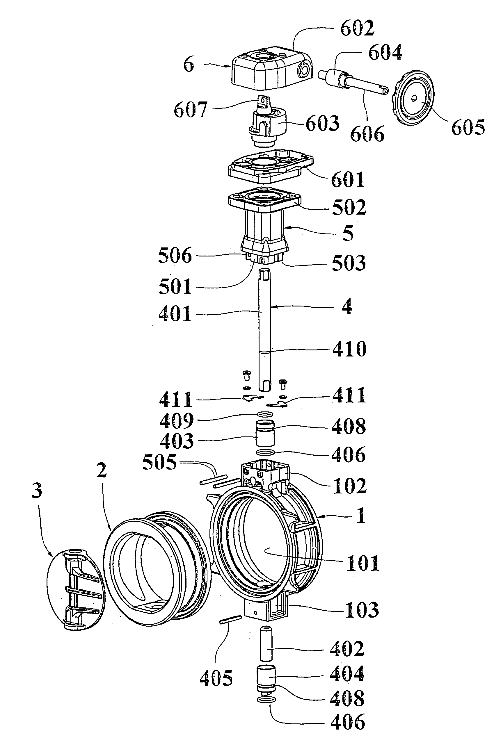
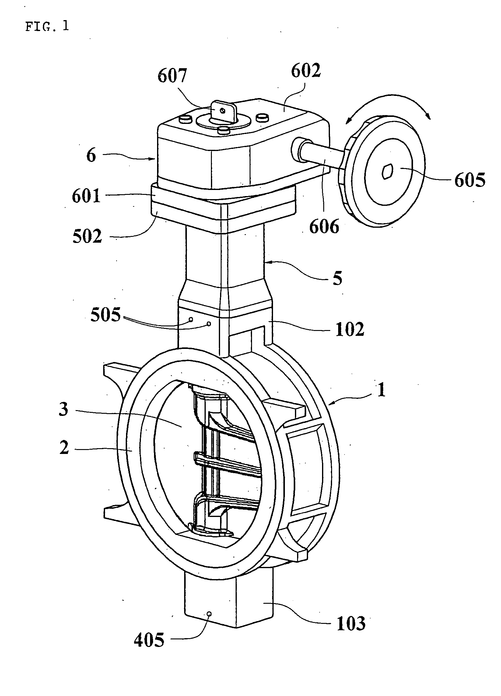
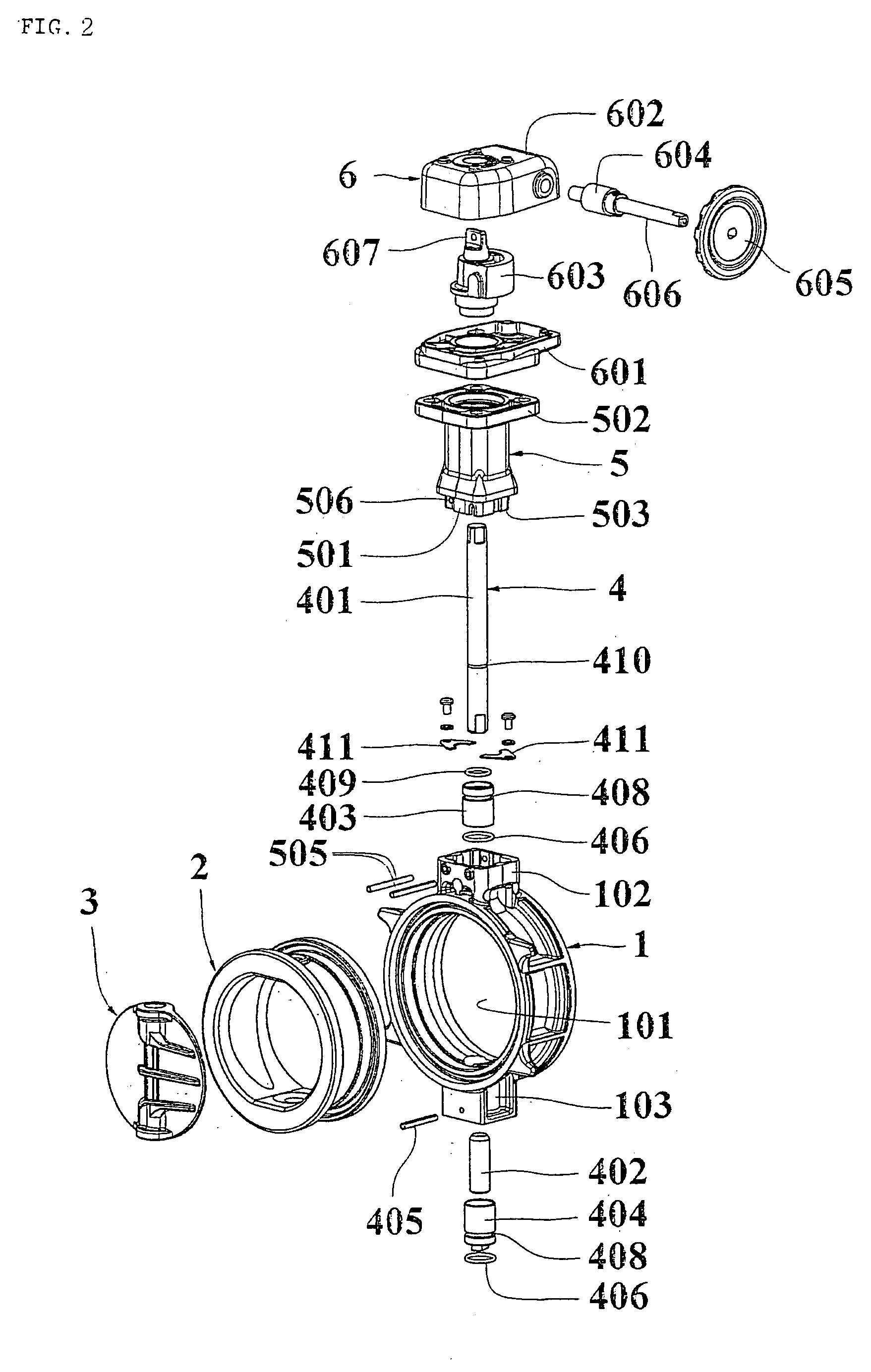
[0051] Referring to FIGS. 1 and 2, a reference number (1) represents a valve body made of aluminum die cast which passes through a flow passage (101). A sheet ring (2) made of elastic sealing material such as rubber is detachably mounted in the valve body (1), and sets a substantial diameter of the flow passage (101). A reference number (3) represents a disk-like valve element which is rotatably and pivotally supported in the sheet ring (2) by a valve rod (4). By rotating the valve element (3), an outer peripheral surface thereof is allowed to come into contact with and separated from an inner peripheral surface of the sheet ring (2), thereby opening and closing the flow passage. The valve rods (4) are rotatably and pivotally supported by valve rod shaft supporting portions (102) and (103) which extends radially outward of the valve body. One of the valve rod (401) extends long from the valve rod shaft supporting portion (102) through a valve shaft cylindrical portion (5) outward. A...


PUM


Abstract

A portion of the one valve rod which extends outward is pivotally supported, the valve shaft cylindrical portion which is connected to the valve rod shaft supporting portion is made of material different from that of the valve body, a slanting surface is formed between the inner peripheral surface and the outer peripheral surface of the sheet ring, an angle and a width formed by the slanting surface and the outer peripheral side surface are the greatest at a position intersecting with the valve shaft at right angles and are the smallest at a position of the valve shaft, a central portion of an inner peripheral surface of the valve body is allowed to project inward to form an engaging projection, the sheet ring is brought into contact with the inner peripheral surface of the valve body under pressure in the opposite sides of the recess groove, the cylindrical bush whose one end is closed is mounted to the other valve rod which pivotally supports the valve element, and the other valve rod is sealed.

Description

TECHNICAL FIELD [0001] The present invention relates to a butterfly valve for opening, closing and controlling a flow passage through which fluid passes. More particularly, the invention relates to a novel improvements of joining a valve body and a valve shaft cylindrical portion which are made of different kind of material, mounting a sheet ring to an inner peripheral surface of the valve body, sealing a valve rod which pivotally supports a valve element, and a gear box of an actuator which drives and rotates the valve element. BACKGROUND ART [0002] A wafer type butterfly valve which is sandwiched and mounted between flanges of a pipe to open and close a pipeline is conventionally known. Such butterfly valves are generally used for controlling fluid which is supplied to a plant equipment in various industrial fields. [0003] As such a butterfly valve, there is a proposed structure in which in order to prevent condensation from being caused on a valve shaft cylindrical portion or an ...

Claims


Application Information

Patent Timeline
IPC IPC(8): F16K1/22F16K1/226F16K27/02
CPCF16K1/221F16K27/0218F16K1/2265F16K1/22
Inventor KAMESAWA, JIRO
Owner TOMOE TECH RES CO LTD
Why Eureka
Try Eureka