Apparatus and method for increasing the performance of a clock-based digital pulse width modulation generator

a technology of clock-based digital pulse width and generator, applied in pulse manipulation, pulse technique, instruments, etc., can solve the problems of signal integrity, system clock can only be increased so much, and the width modulator

Inactive Publication Date: 2005-08-25
TEXAS INSTR INC
View PDF12 Cites 22 Cited by
  • Summary
  • Abstract
  • Description
  • Claims
  • Application Information

AI Technical Summary

Benefits of technology

[0012] The aforementioned and other features are accomplished, according to the present invention, by incorporating a delay line having predetermined number of delay elements coupled series in circuit carrying the transition control signal. The signal generated at the output terminal of a determined number of delay elements can be selected to provide the transition signal. In this manner, the leading edge of the pulse width modulator output signal can be extended a fractional amount of a system clock cycle by the number of selected delay elements. Because delay elements have known stability problems, a circuit is provided to compensate for lack of stability of the delay element.
[0013] Other features and advantages of present invention will be more clearly understood upon reading of the following description and the accompanying drawings and the claims.

Problems solved by technology

When this width is too large, the pulse width modulator will have regulation problems, such as “hunting”, in order to acquire the “correct” duty cycle.
However, the system clock can only be increased so much before the deterioration in the wave form and other parameters begin to compromise the signal integrity.

Method used


Image

  • Apparatus and method for increasing the performance of a clock-based digital pulse width modulation generator
  • Apparatus and method for increasing the performance of a clock-based digital pulse width modulation generator
  • Apparatus and method for increasing the performance of a clock-based digital pulse width modulation generator

Examples


Embodiment Construction

1. Detailed Description of the Figures

[0020]FIG. 1, FIG. 2, and FIG. 3 having been discussed with respect to the related art.

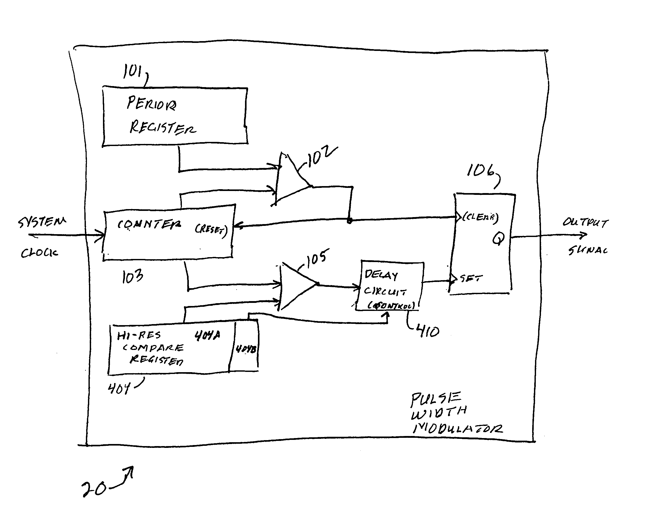
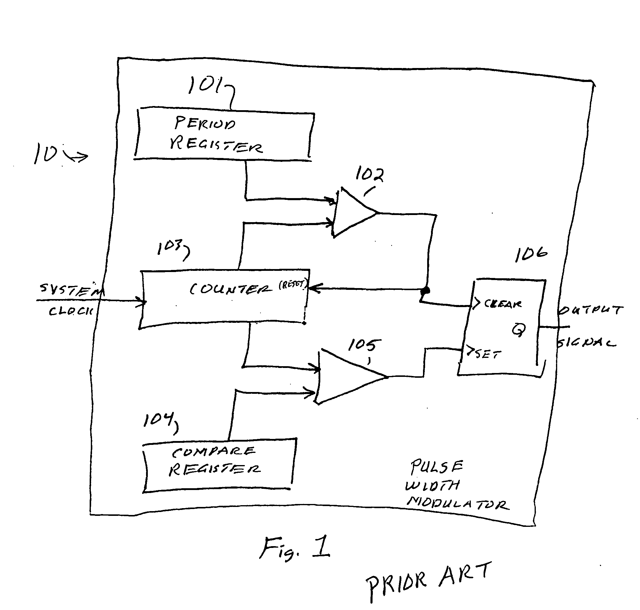
[0021] Referring to FIG. 4, a block diagram of a pulse width modulator 20, according to the present invention, is shown. Comparing FIG. 4 with FIG. 1, the counter 103, the period register 101, the comparators 102 and 105, and the DQ flip-flop 106 operate in a manner similar to the operation described with respect to FIG. 1. However, the compare register 104 is implemented as a hi-res compare register 404. The hi-res compare register 404 is divided into two parts, a register portion 404A analogous to the compare register 104, and register portion 404B. The output terminal of the comparator 105 is applied to an input terminal of delay circuit 410. The output terminal of delay circuit 410 is applied to the set terminal of Q flip-flop 106. The contents of hi-res register portion 404B are applied to a control (set) terminal of delay circuit 410.

[0022] Referring ...


PUM


Abstract

To improve the performance of a pulse width modulator, a delay line having number of delay elements receives a pulse signal from the final clock cycle prior to the generation of the trailing edge of the pulse width modulator signal. Each delay element delays the pulse signal a fraction of the system clock cycle. By controlling the number of delay elements prior to the application of the pulse to the trailing edge-generating component, the trailing edge can be adjusted by increments of the clock cycle determined by the number of delay elements. Because parameters of delay elements can vary, a technique for the calibration of the delay line circuit is disclosed.

Description

[0001] This application claims priority under 35 USC §119(e) (1) of Provisional Application No. 60 / 547,549 (TI-36499PS) filed Feb. 25, 2004.BACKGROUND OF THE INVENTION [0002] 1. Field of the Invention [0003] This invention relates generally to digital circuits and, more particularly, to digital pulse width modulation circuits. [0004] 2. Background of the Invention [0005] The digital pulse width modulator has number of uses in modern digital signal processing, one of the more important being power conversion regulation. The pulse width modulator controls the average power delivered to a destination by controlling a ratio of the time a positive signal is generated during a pulse period to the total period of the pulse. [0006] Referring to FIG. 1, a block diagram of a pulse width modulator 10 according to the prior art is shown. Period register 101 and compare register 104 store a static value. Counter 103 has the system clock applied thereto. The output counter for counter 103 is appl...

Claims


Application Information

Patent Timeline
Patent Type & Authority Applications(United States)
IPC IPC(8): H02M3/335H03K5/156H03K7/08
CPCH03K7/08H03K5/1565
Inventor FIGOLI, DAVID A.
Owner TEXAS INSTR INC
Why Eureka
Try Eureka