Thermal barrier coating material, gas turbine parts and gas turbine

a technology of thermal barrier coating and gas turbine, which is applied in the direction of machines/engines, superimposed coating process, natural mineral layered products, etc., can solve the problems of turbine blades, parts of ceramic layers falling off, and cannot endure such high temperatures

Inactive Publication Date: 2003-05-08
MITSUBISHI HEAVY IND LTD
View PDF0 Cites 9 Cited by
  • Summary
  • Abstract
  • Description
  • Claims
  • Application Information

AI Technical Summary

Problems solved by technology

The turbine blades are made of heat-resistant metal but cannot endure such high temperatures.
However, when the stationary vane and / or the rotor blade of a gas turbine are coated with a thermal barrier coating material formed from a ceramic layer made of YSZ, the inlet temperature of the gas turbine may exceed 1500.degree. C. depending on the type of gas turbine, giving rise to the possibility of a part of the ceramic layer spalling off under harsh operating conditions, thus losing the heat resistance.
Spall-off of the ceramic layer made of YSZ occurs because of insufficient crystalline stability of the YSZ at high temperatures and insufficient durability against high thermal stresses.
In the case in which the thermal barrier coating material comprising the ceramic layer made of YSZ is used on high temperature components such as turbine parts, there has been a problem in that phase transformation occurs in the YSZ due to the exposure to high temperatures over a long period of time, resulting in deterioration of heat insulating performance and volume change that causes stress in the ceramic layer leading to cracks.
Since the transformation from the t phase to the m phase is accompanied by a significant volume change, the YSZ layer is subjected to great stresses that cause cracks.
It is supposed that growth of the cracks causes part of the YSZ layer to spall off, resulting in deterioration of the heat insulating performance of the thermal barrier coating material.
When the Er.sub.2O.sub.3 content is out of the range described above, thermal cycle durability deteriorates significantly.
When the void ratio exceeds 15%, adhesion with the bonding coat becomes weak and the durability decreases.

Method used


Image

  • Thermal barrier coating material, gas turbine parts and gas turbine
  • Thermal barrier coating material, gas turbine parts and gas turbine
  • Thermal barrier coating material, gas turbine parts and gas turbine

Examples


example 1

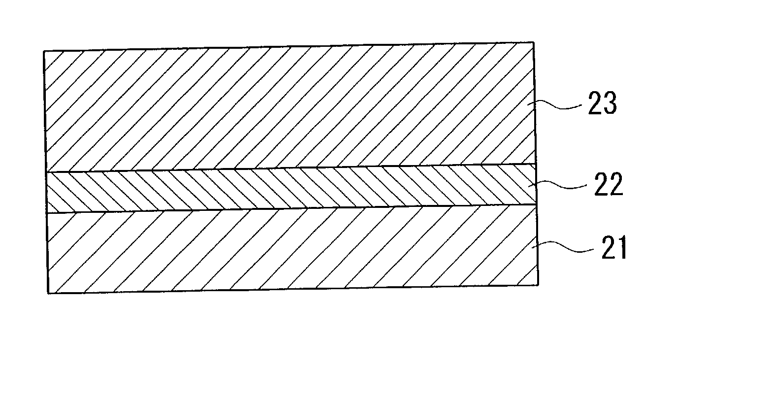
[0043] In this example, samples having ErSZ layers formed from ZrO.sub.2 with varying Er.sub.2O.sub.3 content were fabricated and tested to measure the thermal cycle life, in order to determine the change in the thermal cycle life with the changing quantity of Er.sub.2O.sub.3 content. Ni-based heat-resistant alloy with the composition of Ni--16Cr--8.5Co--1.7Mo--2.6W--1.7T--0.9Nb--3.4Al--3.4Ti was used for the base of the samples. After sand-blasting the base surface with Al.sub.2O.sub.3 particles, the surface was coated with a CoNiCrAlY alloy that has a composition of Co--32Ni--21Cr--8Al--0.5Y by a low-pressure plasma thermal spray process so as to form a bonding coat layer. Then a ceramic layer (ErSZ layer) was formed by an atmospheric plasma thermal spray process on the bonding coat layer made of the CoNiCrAlY alloy, thereby forming the thermal barrier coating material. The Er.sub.2O.sub.3 content in the ceramic layers of different samples (samples Nos. 1 to 12) are shown in Table...

example 2

[0051] Next, in order to study the change in durability with different void ratios in the ceramic layer made of ErSZ, samples were made by forming thermal barrier coating material films, having the ceramic layers of different void ratios shown in Table 2, on bases. Void ratios in the ceramic layers of these samples were set to predetermined values by controlling the thermal spray flow and distance. Samples Nos. 15 to 23 were made same manner as in Example 1, except for controlling the void ratio and setting the Er.sub.2O.sub.3 content to 18% by weight.

[0052] As shown in Table 2, samples Nos. 18 to 20 having void ratios of the ceramic layer within a range from 8% to 15% proved to have higher thermal cycle durability than the thermal barrier coating material film having the ceramic layer made of YSZ of the prior art shown in Table 1.

2TABLE 2 Er.sub.2O.sub.3 content Void ratio after Sample No. (Wt %) thermal spraying Thermal cycle life 15 18 2% 5 16 18 4% 15 17 18 6% 150 18 18 8% 894 1...


PUM

PropertyMeasurementUnit
temperatureaaaaaaaaaa
inlet temperatureaaaaaaaaaa
surface temperatureaaaaaaaaaa

Abstract

A thermal barrier coating material can prevent spall-off from occurring during operation at high temperatures and has a high heat insulating effect. A turbine parts and a gas turbine that are protected with the thermal barrier coating material are also provided. The thermal barrier coating material of the present invention comprises a ceramic layer 23, which is formed on a high temperature heat-resistant alloy base 21 to protect the base 21 from high temperatures, the ceramic layer 23 being applied via a bonding coat layer 22 provided as a metal bonding layer and is made of ZrO2 with Er2O3 added thereto as a stabilizing agent. The turbine parts and the gas turbine of the present invention are coated with the thermal barrier coating material on the surfaces thereof.

Description

[0001] 1. FIELD OF THE INVENTION[0002] The present invention relates to a thermal barrier coating material, a gas turbine parts, and a gas turbine that have high durability and, more particularly, relates to the constitution of a ceramic layer used as a top coat for the thermal barrier coating material.[0003] 2. DESCRIPTION OF THE RELATED ART[0004] It has been attempted in recent years to improve the thermal efficiency of thermal power generation as part of efforts to reduce energy consumption. To improve the thermal efficiency of a gas turbine used in thermal power generation, it is effective to raise the temperature at the gas inlet, which may often be set to about 1500.degree. C. Operating a power generator at such a high temperature requires building stationary vanes and rotor blades that constitute the gas turbine and / or the wall of a combustor with materials that can endure the high temperature. The turbine blades are made of heat-resistant metal but cannot endure such high te...

Claims


Application Information

Patent Timeline
Patent Type & Authority Applications(United States)
IPC IPC(8): F01D5/28C23C4/10C23C28/00C23C30/00F02C7/00
CPCC23C4/105C23C28/3215C23C28/3455Y10T428/12618Y02T50/67Y10T428/1259Y10T428/12611C23C30/00C23C4/11Y10T428/249953Y10T428/249956Y10T428/249967Y02T50/60
Inventor TORIGOE, TAIJIAOKI, SUNAOMORI, KAZUTAKAOKADA, IKUOTAKAHASHI, KOUJI
Owner MITSUBISHI HEAVY IND LTD
Why Eureka
Try Eureka