Home network system and control method for the same

a home network and control method technology, applied in the field of home network systems, can solve the problems of not being able to recognize the connection of the client electric home appliance, the operation initiation message may not reach the home server, etc., and achieve the effect of improving the convenience of using the home network system

Active Publication Date: 2005-08-25
LG ELECTRONICS INC
View PDF10 Cites 78 Cited by
  • Summary
  • Abstract
  • Description
  • Claims
  • Application Information

AI Technical Summary

Benefits of technology

[0022] Accordingly, the home network system can control respective operations of the associated electric home appliances by monitoring respective operation statuses of the electric home appliances connected to the home network system via a network, and receiving operation control commands for the electric home appliances. The home network system also periodically identifies the connection status of the electric home appliances, each of which is maintained in a standby state because there is no associated operation control command received by the home network system, thereby updating operation statuses and connection statuses of the electric home appliances. Thus, it is possible to achieve an enhancement in convenience in using the home network system.

Problems solved by technology

In the conventional home network system having the above-mentioned configuration, there may be a problem in that, when the network N is instable, a control signal from the home server HS may not be transmitted to an associated one of the client electric home appliances C1 to C4.
Where the network is instable, however, the operation initiation message may not reach the home server.
In this case, the home server cannot recognize the connection of the client electric home appliance.

Method used


Image

  • Home network system and control method for the same
  • Home network system and control method for the same
  • Home network system and control method for the same

Examples


first embodiment

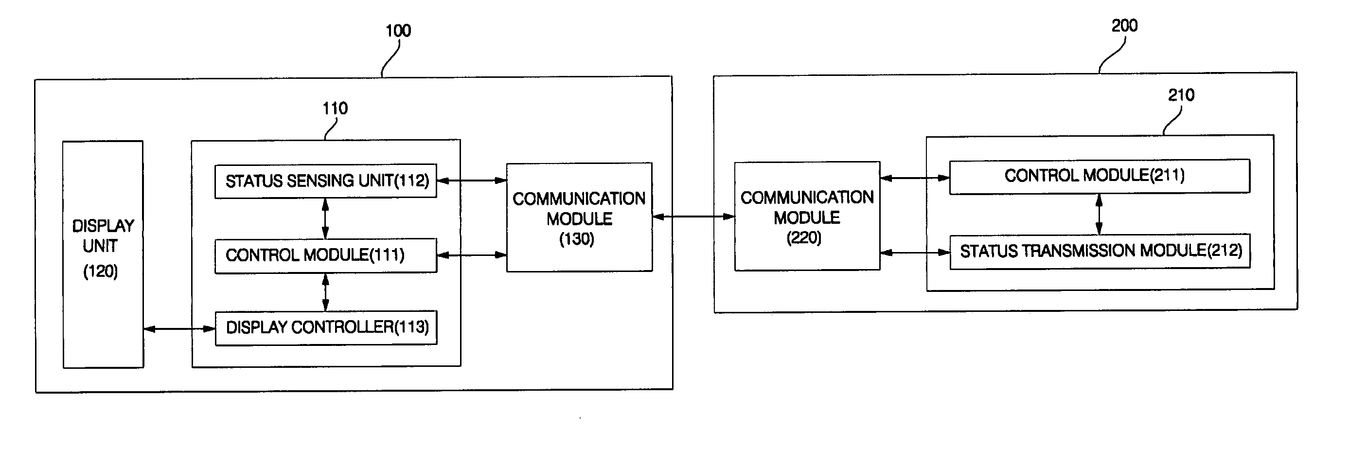
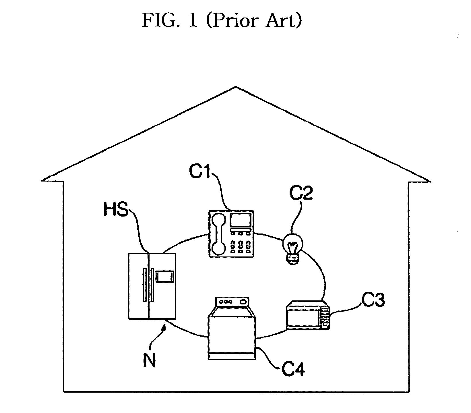
[0032] As shown in FIG. 3, the home network system according to the present invention includes one or more electric home appliances 200 connected to a network. Each electric home appliance 200 periodically transmits an alive message through the network in order to inform of the fact that the electric home appliance 200 is in operation. The home network system also includes a home server 100 connected to the network such that the home server 100 transmits / receives messages to / from each electric home appliance 200 via the network. Where there is no alive message from one of the electric home appliances 200 received by the home server 100 for a predetermined time, the home server 100 also transmits an operation identification request message to the electric home appliance 200 transmitting no alive message.

[0033] The network, to which the home server 100 and electric home appliances 200 are connected, may be a local area network (LAN), a typical one of which is an Ethernet, a wireless c...

second embodiment

[0042] In accordance with the present invention, the home server 100 includes an input unit 140, to which operation commands adapted to control operations of respective electric home appliances 200 are inputted from the outside of the home network system.

[0043] In response to an operation command inputted through the input unit 140, the server controller 110 generates a control signal for controlling an associated one of the electric home appliances 200. The input unit 140 may be implemented by an external input device such as a keyboard, a mouse, or a tablet, so as to allow inputting of an external message. Alternatively, the input unit 140 may be implemented by a touch screen internally provided in the home server 100 while being integral with an output unit included in the home server 100.

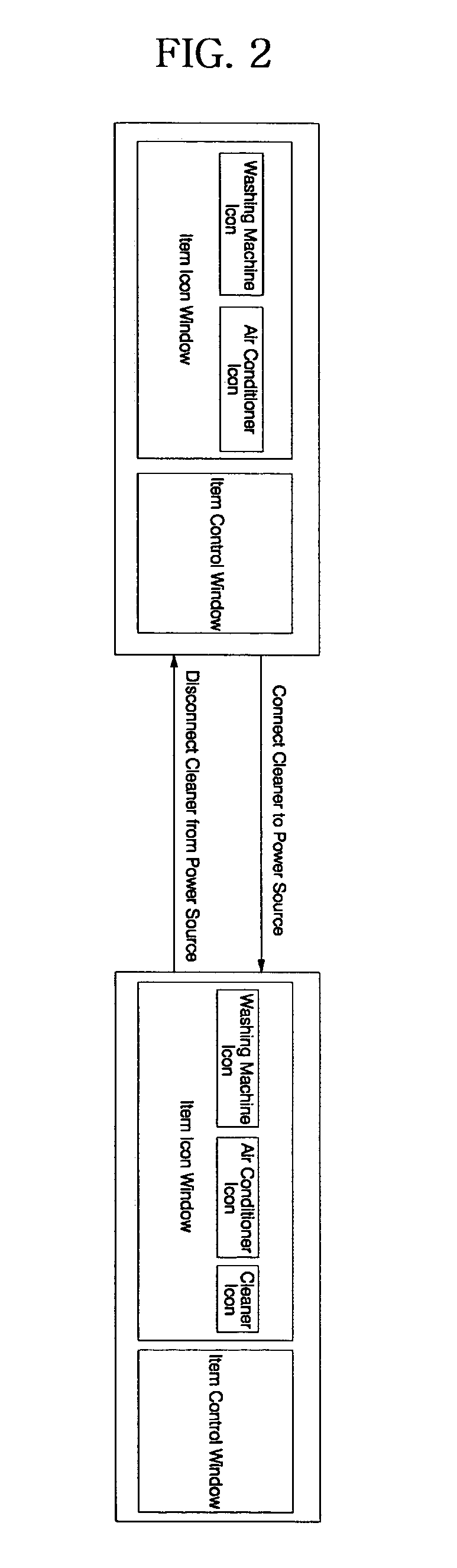
[0044] Accordingly, the user can select a desired one of the electric home appliances 200 to control the selected electric home appliance 200 by touching the icon of the selected electric home ...

third embodiment

[0046] In accordance with the present invention, the above described input unit and display unit may be implemented by an independent input / output device 300, which may be a web pad directly connected to the home server 100 by means of a particular connector.

[0047] The input / output device 300 includes a network connector 330 connected to the home server 100, and adapted to input or output messages, a display controller 310 adapted to display a message received from the home server 100 in the form of an icon, and input unit 320 adapted to input control commands for controlling operations of respective electric home appliances 200 connected to the home server 100 and the network.

[0048] The network connector 330 may be included in the home server 100. The network connector 330 may perform transmission and reception of data through a universal serial bus (USB) port. Also, the network connector 330 may perform the data transmission and reception through the above-described network or a ...


PUM


Abstract

A home network system including one or more electric home appliances connected to a network, each of the electric home appliances periodically transmitting an alive message through the network to inform of the fact that the electric home appliance is in operation, and a home server connected to the network such that the home server transmits / receives messages to / from each electric home appliance via the network to control the electric home appliance while monitoring the status of the electric home appliance. The home server transmits an operation identification request message to the electric home appliance when no alive message from the electric home appliance is received by the home server for a predetermined time. Accordingly, the home network system can identify respective operation statuses of the electric home appliances, and control respective operations of the electric home appliances, while periodically identifying the connection status of the electric home appliances, each of which is maintained in a standby state because there is no associated operation control command received by the home network system, thereby updating operation statuses and connection statuses of the electric home appliances. The invention also provides a method for controlling the home network system. Thus, an enhancement in convenience in using the home network system is achieved.

Description

BACKGROUND OF THE INVENTION [0001] 1. Field of the Invention [0002] The present invention relates to a home network system and a control method for the same, and more particularly to a home network system capable of identifying operation statuses of electric home appliances connected to the home network system via a network, and receiving operation control commands, thereby controlling operations of the associated electric home appliances, while periodically receiving alive messages from the electric home appliances, each of which is maintained in a standby state because there is no associated operation control command received by the home network system, thereby displaying connected statuses of the standby electric home appliances, and a control method for this home network system. [0003] 2. Description of the Related Art [0004]FIG. 1 is a schematic view illustrating a conventional home network system. [0005] Recently, distribution of home network systems has been increased. Such a...

Claims


Application Information

Patent Timeline
Patent Type & Authority Applications(United States)
IPC IPC(8): H04L12/24G05B15/02G05B23/02H04L12/00H04L12/26H04L12/28
CPCG05B15/02H04L12/2803H04L12/282H04L2012/285H04L43/0811H04L43/0817H04L43/10H04L12/66E01D19/00
Inventor LEE, YEON KYOUNG
Owner LG ELECTRONICS INC
Why Eureka
Try Eureka