
Control and supply system

a supply system and control technology, applied in the direction of power distribution line transmission, emergency protective arrangements for limiting excess voltage/current, single ac network with different frequencies, etc., can solve the problems of further devices, which are very complex and expensive, and are needed for this correction. , to achieve the effect of simple data coupling

Active Publication Date: 2005-08-25
COOPER CAMERON CORP +1
View PDF83 Cites 16 Cited by
  • Summary
  • Abstract
  • Description
  • Claims
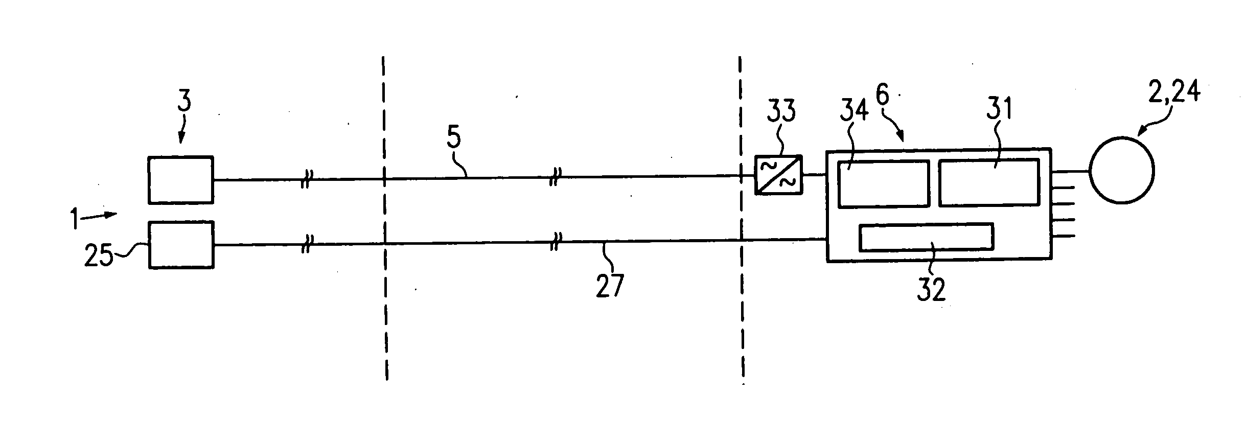
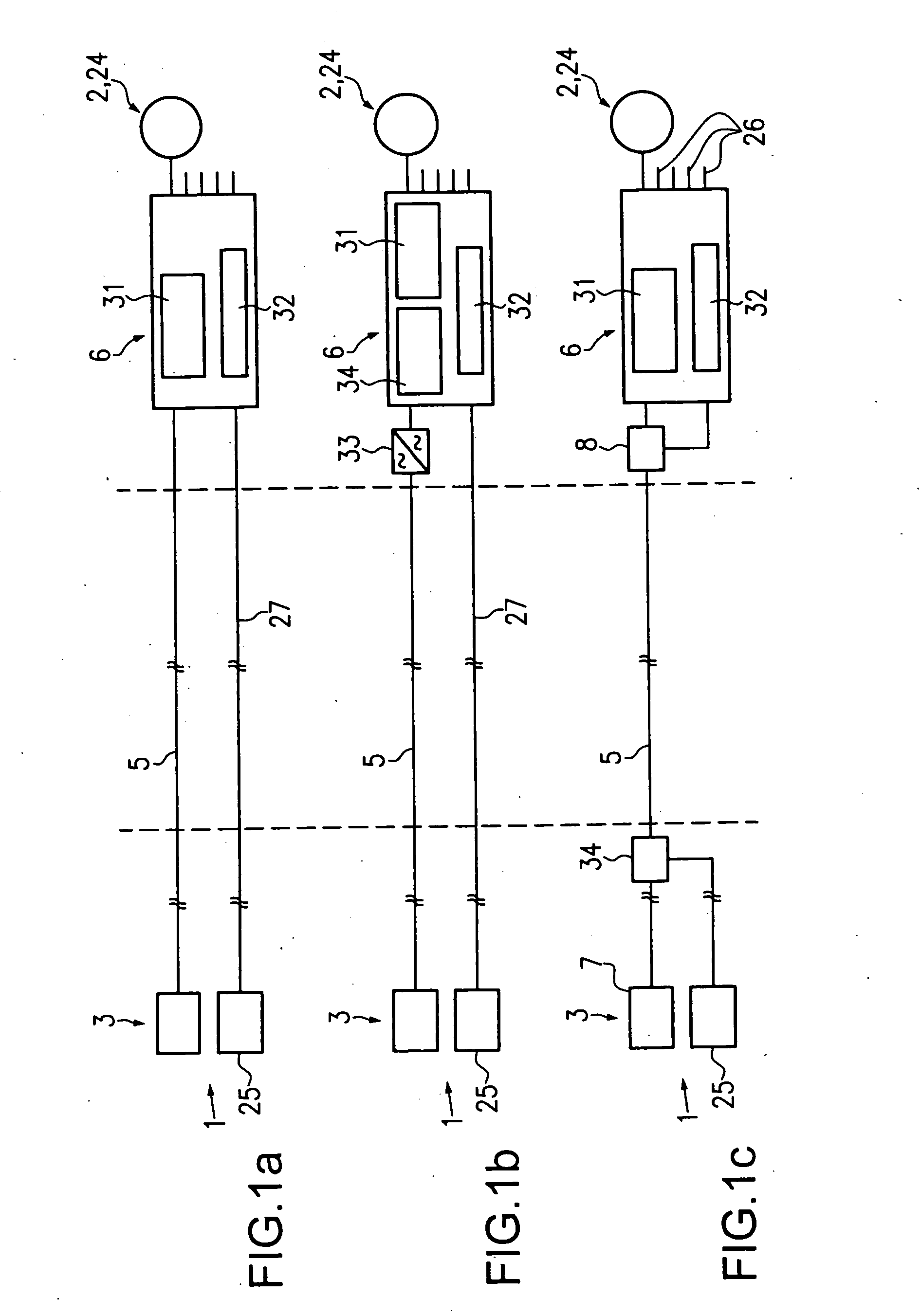
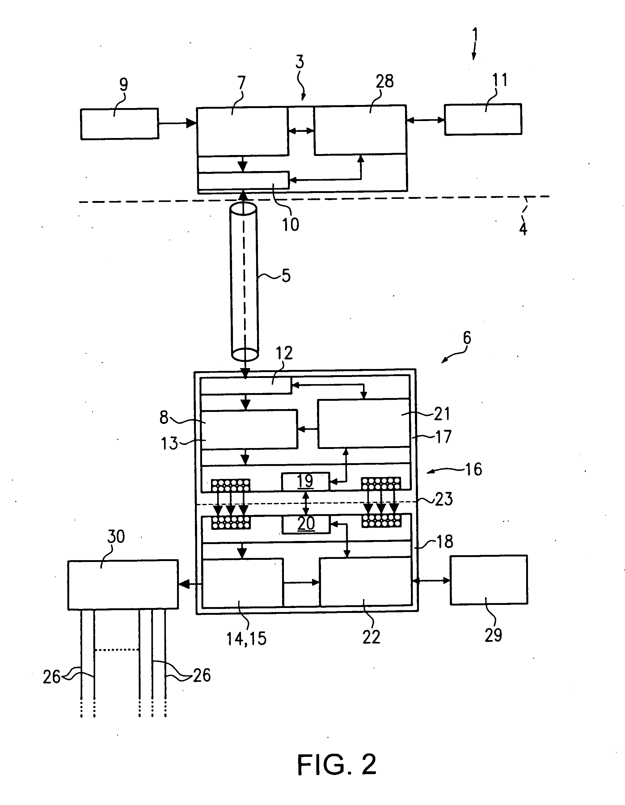
  • Application Information

AI Technical Summary

Benefits of technology

The invention is a control and supply system for a subsea cable production facility. The system uses a DC / AC converter to convert direct voltage into alternating voltage for transmission over the subsea cable. This reduces the complexity of the system and allows for more efficient use of the cable. The system also includes a data modulation device for transmitting data over the subsea cable. The system is simple and cost-effective, with higher efficiency and better performance. The use of inductive coupling between the subsea cable and electrical devices prevents damage to the equipment and allows for easy recovery and reuse of components. The system also allows for simultaneous interchange of data over the air gap between the coil half-cores.

Problems solved by technology

A disadvantage with this known control and supply system is that, for example, for a supply of an electrical device with 240 VAC and with an original voltage feed of 600 VAC for the transmission of the appropriate power to the electrical devices and, for example, a length of subsea cable of 30 or 50 km, a cross-sectional area of 100 to 200 mm2 is needed for the cable.
Further devices, which are very complex and expensive, are needed for this correction.

Method used


Image

  • Control and supply system
  • Control and supply system
  • Control and supply system

Examples


Embodiment Construction

[0009] The object of the invention is to improve a control and supply system of the type mentioned at the beginning such that with less complexity, higher efficiency and better system usage, supply is possible over larger distances.

[0010] This object is solved in relationship with the characteristics of the generic term of claim 1 such that the voltage supply and control device for the production of a direct voltage for feeding into the subsea cable comprises at least one AC / DC converter, the control and actuating device is associated with at least one DC / DC or DC / AC converter for converting the direct voltage transmitted by the subsea cable into a direct voltage or alternating voltage and the voltage generated thereby can be transmitted to the electrical devices via the connecting lines. This means that according to the invention direct voltage is transmitted via the long subsea cables, whereby the conversion from alternating voltage into direct voltage or vice versa from direct v...


PUM


Abstract

The invention relates to a control and supply system for electrical devices, comprising at least one voltage supply and control device above sea level, a subsea cable connecting said voltage supply and control device with the electrical devices, and a control and actuating device which is associated essentially in situ with the electrical devices. The aim of the invention is to improve one such control and supply system in such a way that supplies are possible over larger distances, using fewer means, obtaining higher efficiency and making better use of the system. In order to achieve this, the voltage supply and control device comprises at least one AC / DC converter for producing a direct voltage in order to feed the subsea cable, the control and actuating device is associated with at least one DC / DC or DC / AC converter for converting the direct voltage transmitted by the sub-sea cable into a direct voltage or an alternating voltage, and the voltage generated thereby can be transmitted to the electrical device via the connecting line.

Description

BACKGROUND OF THE INVENTION [0001] The invention relates to a control and supply system for electrical devices, comprising at least one voltage supply and control device above sea level, a subsea cable connecting said voltage supply and control device with the electrical devices, and a control and actuating device which is associated essentially in situ with the electrical devices. [0002] Such control and supply systems are used, for example, in the production of natural gas and mineral oil. In this respect, the application may take place with terrestrial and maritime drilling wells. [0003] With maritime wells one part of the control and supply system is arranged on a platform above the sea surface. This part is in particular a voltage supply and control device which is connected via a subsea cable to the control and actuating device below the sea surface or also on the sea bed. The control and actuating device is connected to various electrical devices, such as motors, electrical a...

Claims


Application Information

Patent Timeline
Patent Type & Authority Applications(United States)
IPC IPC(8): H02J3/36H02J1/00H02J5/00
CPCY02E60/60H02J3/36H02J2310/12H02M3/1584Y02P80/14
Inventor BIESTER, KLAUSKUNOW, PETER
Owner COOPER CAMERON CORP
Learn More