Distributed dynamic routing

a dynamic routing and distribution technology, applied in the field of telecommunications, can solve the problems of routers being very complex, and routing being inevitably complicated

Active Publication Date: 2005-08-25
XYLON LLC
View PDF10 Cites 5 Cited by
  • Summary
  • Abstract
  • Description
  • Claims
  • Application Information

AI Technical Summary

Benefits of technology

[0028] As compared to the prior art, the present invention has the advantage that it enables the implementation of very efficient distributed routers. The efficiency is based on the fact that just one routing decision is made for a packet entering an internal telecommunication network. In other words, as the packet arrives at the source edge device, a decision is made at the same time as to what target edge device the packet is routed to. Based on the made routing solution, the packet is transmitted directly to the target edge device via an internal telecommunication network at the L2 layer level. Contrary to conventional routing, the packet thus does not travel on its way through the network via several different routers, in each of which, a new routing decision would be made at the L3 layer level.
[0029] Further, the routing in accordance with the present invention is very fault tolerant because as the packet is transmitted along the whole way from the source edge device to the target edge device at the L2 layer level, the detection of faults, locating them and recovering from them can be performed at the L2 layer level in the order of milliseconds, which is considerably faster than if these procedures had to be performed at the L3 layer level, like in conventional routing.

Problems solved by technology

The problem with the conventional routing is, however, inefficiency, resulting from the fact that the routing decision is made for each packet in each router.
Further, from the large number of routing nodes follows that the routers will inevitably be very complicated in order to achieve a bearable performance.
Therein, however, the different flows must be classified and the status data of each flow must be maintained in each router, making the routers very complex.
Further, even in flow routing, the detection of faults, locating them and recovering from them must be performed at the L3 layer level, which is slow.
Further, the state of each path must be maintained in each router, making the routers very complex.
Further in the case of MPLS routing, the TE routing (Traffic Engineering, TE) and fault tolerance are complicated.
Further, the MPLS routing uses pre-configured paths, resulting in limited dynamics.

Method used


Image

  • Distributed dynamic routing
  • Distributed dynamic routing
  • Distributed dynamic routing

Examples


Embodiment Construction

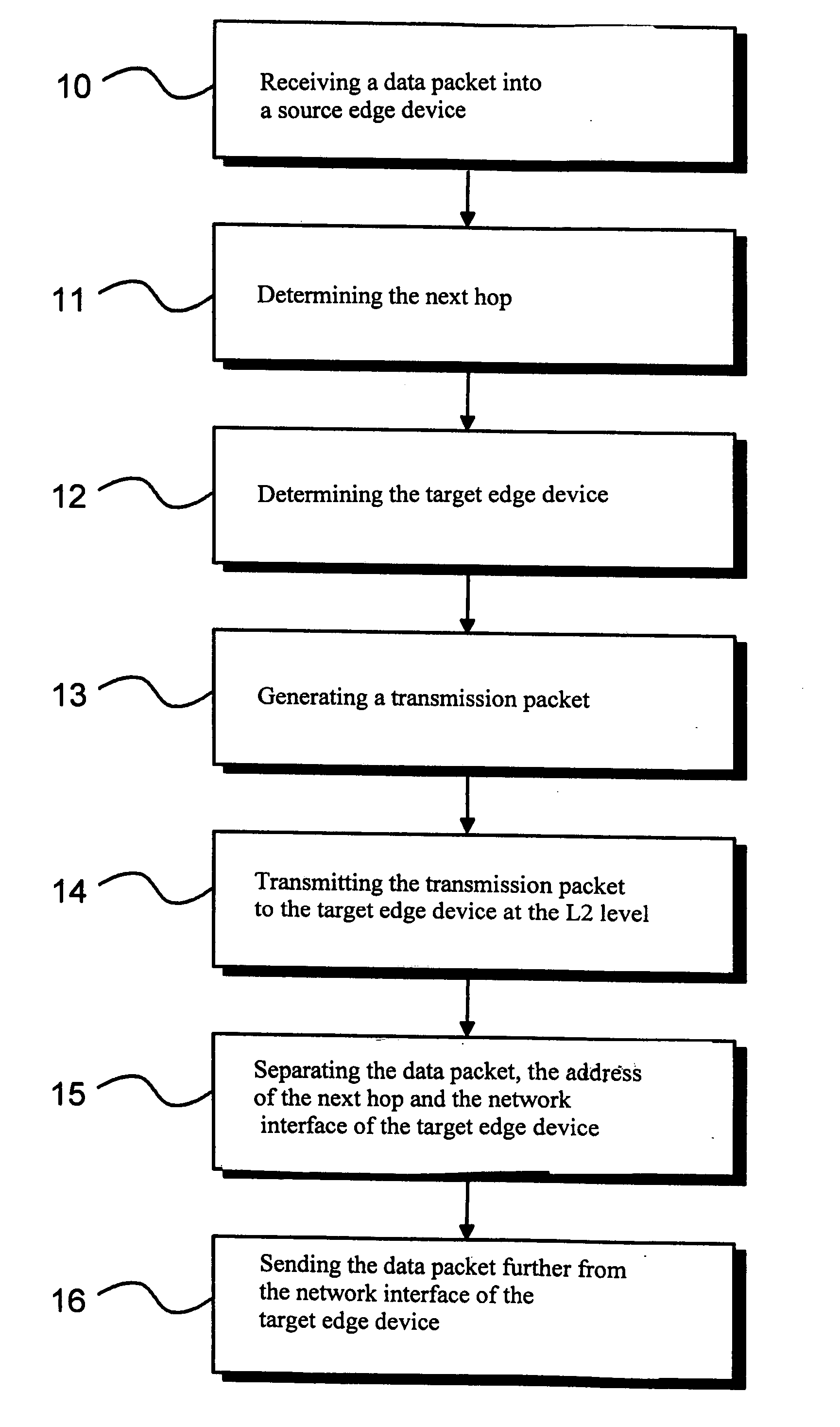
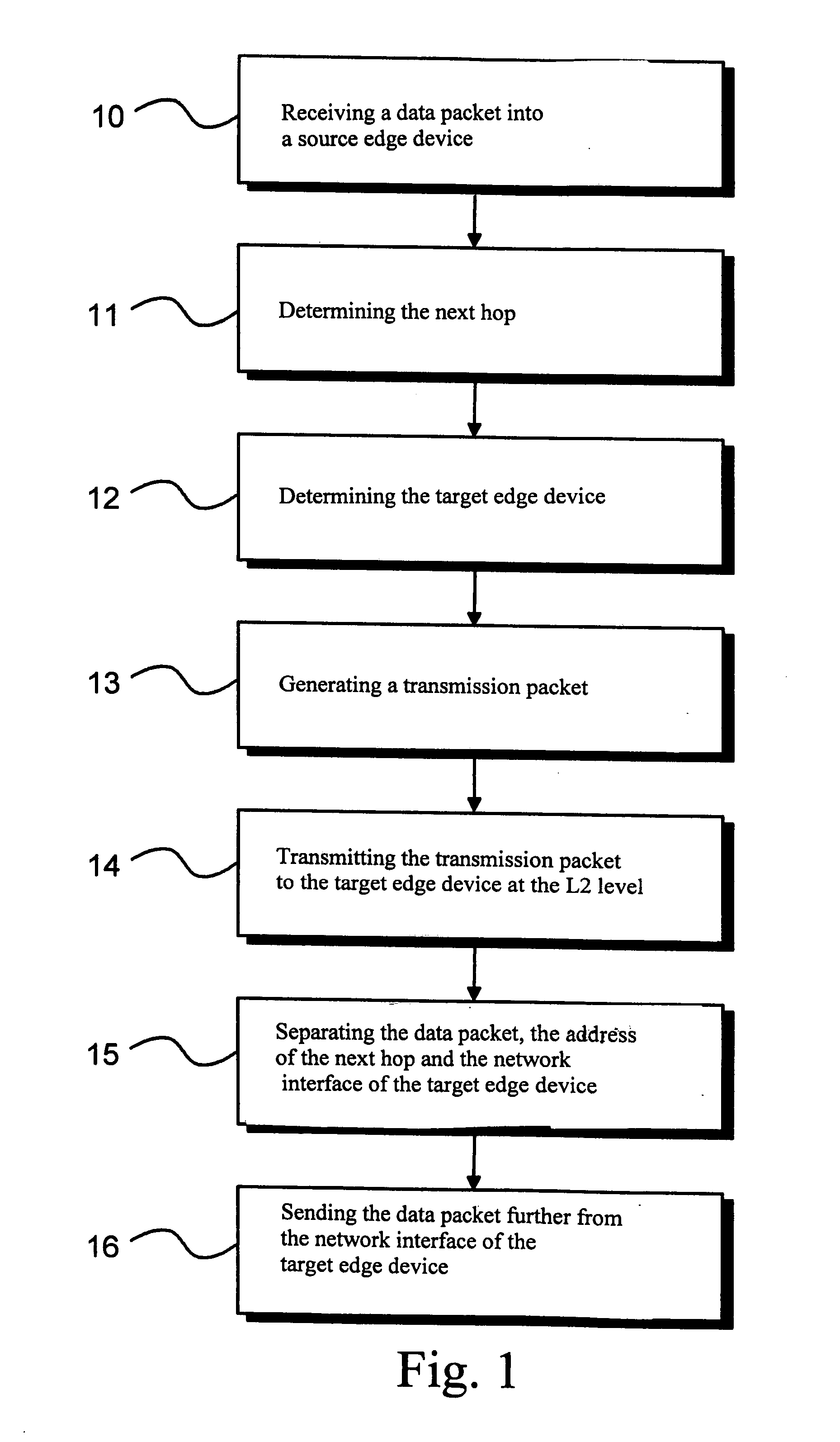
[0035]FIG. 1 is a flow chart describing, by way of example, one method of the invention, by means of which method packets are routed in a distributed and dynamic manner via one or more internal packet-switched telecommunication networks.

[0036] In the method shown in FIG. 1 by way of example, a data packet is received from an external packet-switched telecommunication network to a source edge device, step 10. Next, there is determined in the source edge device the next-hop address, corresponding to the destination address prefix of the received data packet, step 11.

[0037] Further, the method as shown in FIG. 1 by way of example determines the address and network interface of the target edge device corresponding to the next hop determined in the source edge device, step 12. Thereafter, at step 13, there is formed in the source edge device a transmission packet addressed to the determined target edge device comprising the received data packet, as well as the determined next-hop addre...


PUM


Abstract

In the present invention, packets are routed in a distributed and dynamic manner via an internal packet-switched telecommunication network comprising edge devices. A data packet is received from an external telecommunication network to a source edge device, wherein there is determined the address of the next-hop corresponding to the destination address prefix of the received data packet. The address and network interface of the target edge device corresponding to the determined next hop are determined and there is generated a transmission packet addressed to the determined target edge device, the transmission packet comprising the received data packet and the determined address of the next hop and the determined network interface of the target edge device. The generated transmission packet is transmitted from the source edge device to the target edge device via one or more internal telecommunication networks at the data link layer level. The data packet is sent further via the network interface of the target edge device based on the next-hop address in question.

Description

FIELD OF THE INVENTION [0001] The invention relates to telecommunications. In particular, the invention relates to a novel and advanced method and system for routing packets in a distributed and dynamic manner. PRIOR ART [0002] Known in prior art are numerous routing arrangements for packet-switched telecommunication networks such as networks implementing the Internet protocol (IP). [0003] A telecommunication network comprises a set of nodes and a medium connecting them. In a packet-switched telecommunication network, the data to be transmitted from the source node to the destination node usually is divided into a set of data packets, which are each transmitted via their own routes to the destination node. Usually the source node and the destination node are disposed in different networks, so the data packets may travel via several different networks. [0004] In the prior art, an individual network typically comprises numerous nodes implementing the routing function i.e. routers. Whe...

Claims


Application Information

Patent Timeline
Patent Type & Authority Applications(United States)
IPC IPC(8): H04L12/46H04L12/56H04L12/66
CPCH04L12/4608H04L12/462H04L12/4633H04L2212/0025H04L45/00H04L45/50H04L12/66H04L2212/00
Inventor SEPPANEN, KARI
Owner XYLON LLC
Why Eureka
Try Eureka