Light guide plate with subwavelength grating and backlight module using the same

a technology of light guide plate and subwavelength grating, which is applied in the direction of planar/plate-like light guide, lighting and heating apparatus, instruments, etc., can solve the problems of reducing the light utilization efficiency of light guide plate. , to achieve the effect of high light utilization efficiency and high uniformity of outgoing ligh

Inactive Publication Date: 2005-08-25
GOLD CHARM LTD
View PDF4 Cites 17 Cited by
  • Summary
  • Abstract
  • Description
  • Claims
  • Application Information

AI Technical Summary

Benefits of technology

[0009] An object of the present invention is to provide a light guide plate which has a high light utilization efficiency and which yields high uniformity of outgoing light.

Problems solved by technology

However, when the light beams enter the light guide plate 105 through the light incident surface, part of the light beams are reflected by the light incident surface and lost.
This reduces the light utilization efficiency of the light guide plate 105.
Firstly, the anti-reflection film is based on the principle of multi-light interference, and therefore can only provide anti-reflection in a narrow wavelength band.
Thus the anti-reflection film has limited efficacy in reducing loss of light at the light incident surface 21.
As a result, the reflection capability of the anti-reflection film is reduced.

Method used


Image

  • Light guide plate with subwavelength grating and backlight module using the same
  • Light guide plate with subwavelength grating and backlight module using the same
  • Light guide plate with subwavelength grating and backlight module using the same

Examples


first embodiment

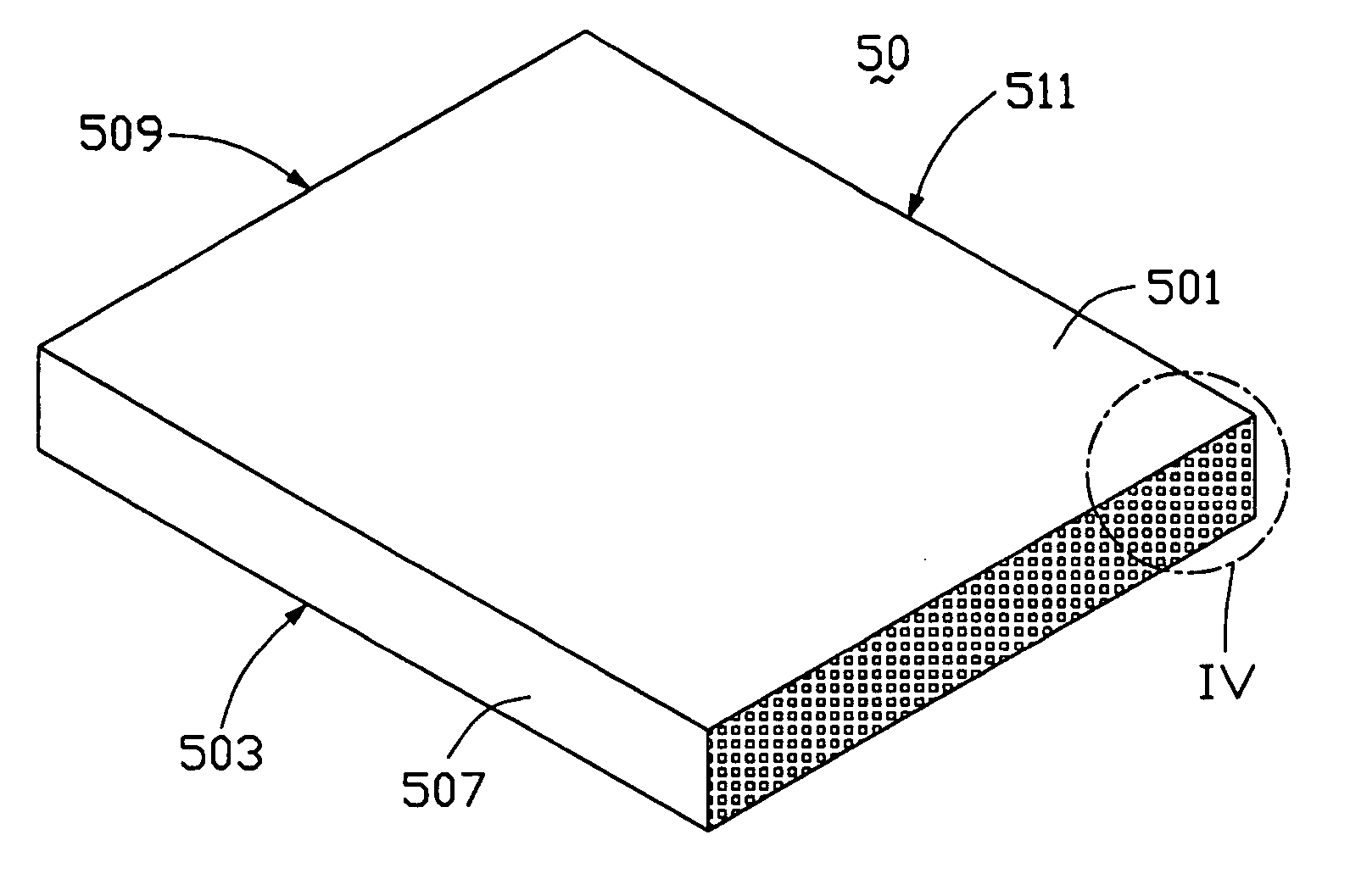
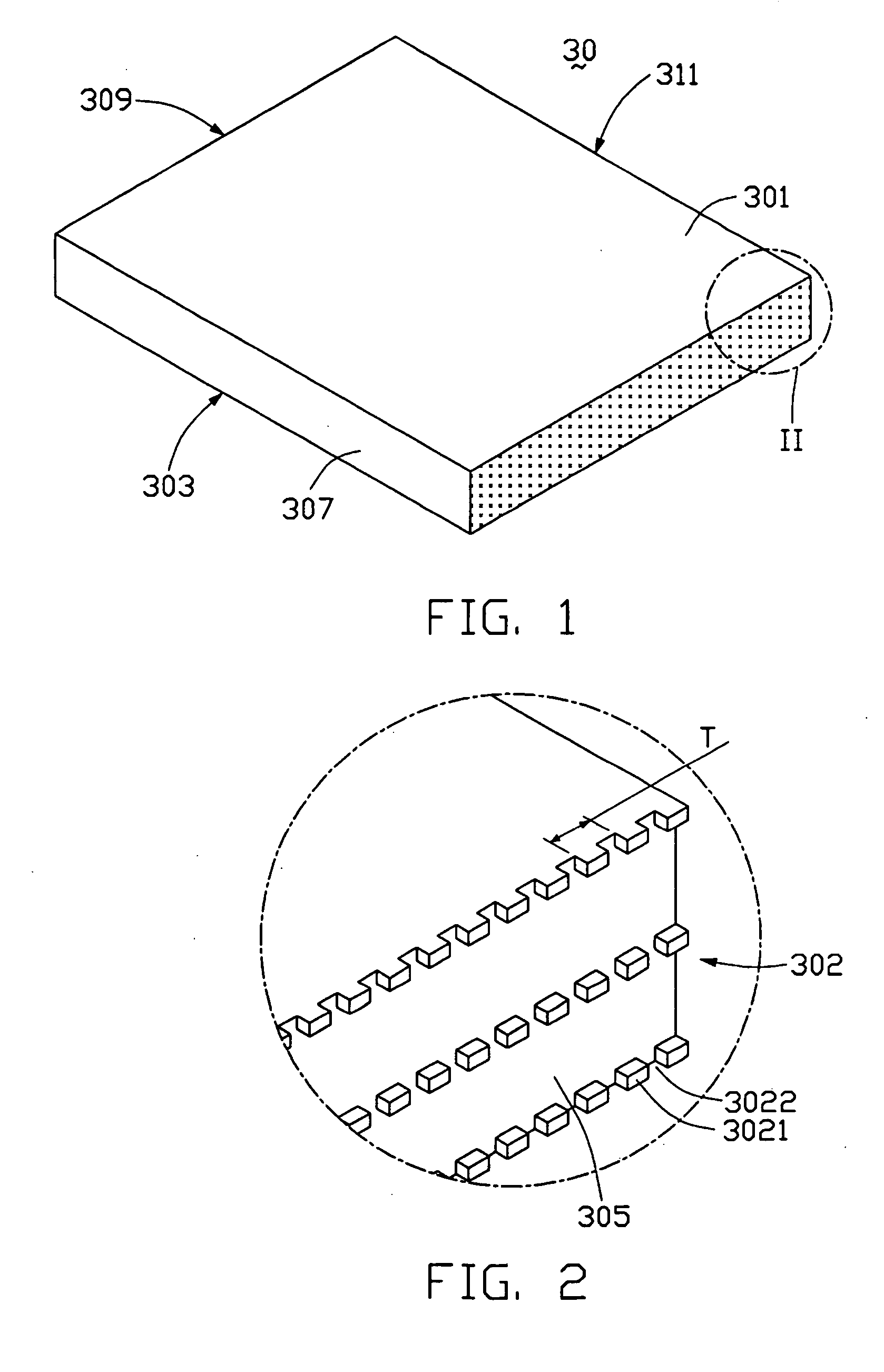
[0022] Referring to FIGS. 1 and 2, a light guide plate 30 according to the present invention is shown. The light guide plate 30 comprises a light incident surface 305, a bottom surface 303 perpendicular to the light incident surface 305, a light emitting surface 301 opposite to the bottom surface 303, and a plurality of side surfaces 307, 309 and 311. A subwavelength grating 302 is formed on the light incident surface 305. The light incident surface 305 receives light beams from a light source (not shown) adjacent thereto, and the light emitting surface 301 emits the light beams for illuminating a liquid crystal display panel (not shown).

[0023] In the preferred embodiment, the light guide plate 30 is made of polymethyl methacrylate (PMMA) resin. Alternatively, transparent glass or another kind of synthetic resin may be used to make the light guide plate 30.

[0024] A plurality of diffusion dots (not shown) are formed on the bottom surface 303 of the light guide plate 30, to make the ...

second embodiment

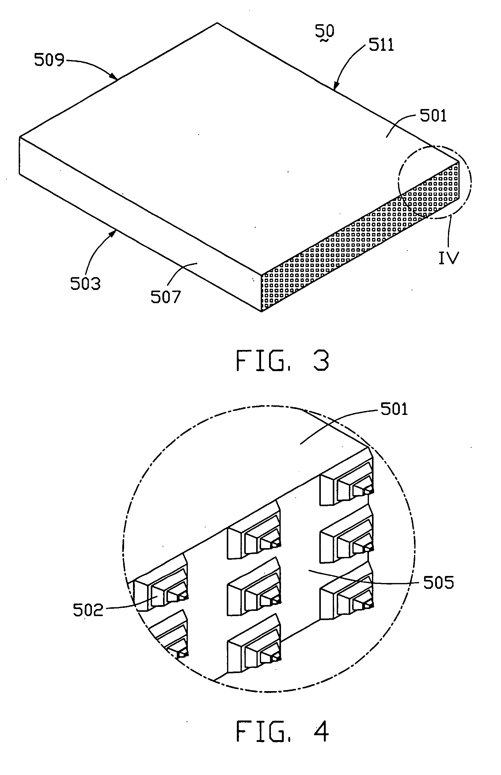
[0029] Referring to FIGS. 3-4, a light guide plate 50 according to the present invention is similar to the light guide plate 30. The light guide plate 50 comprises a light emitting surface 501, a bottom surface 503, a light incident surface 505, and side surfaces 507, 509 and 511. The light incident surface 505 has a two-dimensional subwavelength grating 502 comprising first portions (not labeled) and second portions (not labeled). The first portions have a substantially stepped pyramidal shape.

[0030] Referring to FIG. 5, a backlight module 70 comprises a light source 701, the light guide plate 30, a diffusion plate 704, a prism plate 705 and a light reflective plate 703. The light source 701 is a CCFL, and is disposed adjacent to the light incident surface 305 of the light guide plate 30.

[0031] In an alternative embodiment of the present invention, the subwavelength grating can be a one-dimensional grating.


PUM


Abstract

A light guide plate (30) has a light incident surface (305) for receiving light, a light emitting surface (301) for emitting light, a bottom surface (303) opposite to the light emitting surface, and side surfaces (307, 309, 311). A subwavelength grating (302) is formed on the light incident surface for diffracting the light. The subwavelength grating is a zeroth-order grating which covers a wide wavelength band and diffracts the light into zeroth-order waves. So that the light guide plate has a high light utilization efficiency and yields high uniformity of outgoing light.

Description

BACKGROUND OF THE INVENTION [0001] 1. Field of the Invention [0002] The present invention relates to a light guide plate utilizing a subwavelength grating for controlling light transmission, and a backlight module for a liquid crystal display using such a light guide plate. [0003] 2. Description of Prior Art [0004] Liquid crystal displays (LCDs) commonly use a backlight module to provide illumination. Referring to FIG. 6, a conventional backlight module includes a light source 101, a light guide plate 105, a reflective plate 103, a diffusion plate 107 and a prism plate 109. The light source 101 is typically a cold cathode fluorescent lamp (CCFL). The light guide plate 105 distributes light beams from the light source 101, to provide substantially planar illumination to the LCD. [0005] Light beams typically enter the light guide plate 105 at a light incident surface. The light beams may propagate between a bottom surface and a light emitting surface toward an opposite end surface of ...

Claims


Application Information

Patent Timeline
Patent Type & Authority Applications(United States)
IPC IPC(8): F21V8/00
CPCG02B6/0016
Inventor YU, TAI-CHERNGLEU, CHARLESCHEN, GA-LANE
Owner GOLD CHARM LTD
Why Eureka
Try Eureka