Method for manufacturing magnetic recording medium

a manufacturing method and magnetic recording technology, applied in the direction of magnetic materials, magnetic bodies, and support parts, can solve the problems of difficult to precisely control the amount of processing (thickness) in the order of 1 to 2 nm, increase the density of the areal by a conventional improvement method, and the recording and reproducing characteristics become worse. , to achieve the effect of preventing the increase of the height difference, high flattening effect, and increasing the efficiency of the whole manufacturing process

Inactive Publication Date: 2005-08-25
TDK CORPARATION
View PDF34 Cites 10 Cited by
  • Summary
  • Abstract
  • Description
  • Claims
  • Application Information

AI Technical Summary

Benefits of technology

[0011] In view of the foregoing problems, various exemplary embodiments of this invention provide a method for efficiently manufacturing a magnetic recording medium, which has a recording layer formed in a concavo-convex pattern, and a sufficiently flat surface to realize high recording and reproducing precision.
[0012] To solve the foregoing problems, the present invention uses dry etching in a flattening step. Also, an etching condition is set so as to substantially equalize an etching rate of a non-magnetic material with an etching rate of a recording layer with respect to the dry etching. The dry etching tends to selectively remove a protruding portion of a deposit quicker than the other portions, so that it is possible to realize a high flattening effect. Also, the dry etching can easily control the amount of processing than a CMP method. Furthermore, the etching rate of the non-magnetic material is substantially set to be equal to the etching rate of the recording layer. If a part of the recording layer is removed together with the non-magnetic material after the non-magnetic material above the recording layer is completely removed, it is possible to prevent increase in difference in the height between the top face of the recording layer and the top face of the non-magnetic material.
[0025] According to the present invention, since the dry etching is used in the flattening step, it is possible to obtain a high flattening effect. Also, the etching condition is set so as to substantially equalize the etching rate of the non-magnetic material with the etching rate of the recording layer. Therefore, if a part of the recording layer is removed together with the non-magnetic material after the non-magnetic material above the recording layer is completely removed, it is possible to prevent increase in difference in the height between the top face of the recording layer and the top face of the non-magnetic material. Using the dry etching does not need cleaning of slurry and the like. Furthermore, combining the dry etching with another dry process makes it possible to increase efficiency in the whole manufacturing process.

Problems solved by technology

However, problems such as processing limits of magnetic head, side fringes due to the spread of a magnetic field, and crosstalk have become revealed, so that increase in the areal density by a conventional improvement method has reached its limitation.
When the surface of the medium includes the concavo-convex pattern, on the other hand, there are cases where recording and reproducing characteristics become worse because the flying height of a head slider is unstable.
In the CMP method, however, it is difficult to precisely control the amount of processing (thickness) in the order of 1 to 2 nm.
Accordingly, there is a problem that combining the CMP method and a dry process such as a processing process of the recording layer makes it complicated to convey an object to be processed and the like, so that the efficiency of the whole manufacturing process becomes worse.
When the CMP method is used, there is also a problem that slurry reacts with the recording layer and the magnetic characteristic of the recording layer tends to be degraded.
Furthermore, there is a problem that using the CMP method takes much time and cost for cleaning and the like, because the slurry has to be removed.

Method used


Image

  • Method for manufacturing magnetic recording medium
  • Method for manufacturing magnetic recording medium
  • Method for manufacturing magnetic recording medium

Examples


working example 1

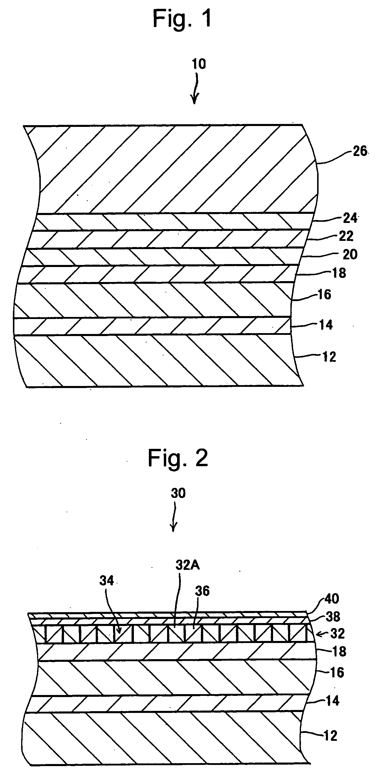
[0091] The magnetic recording medium 30 was manufactured in a way of the foregoing first exemplary embodiment. To be more specific, the recording layer 32 was formed into the following concavo-convex pattern.

[0092] Pitch: 150 nm

[0093] Width of convex portion: 95 nm

[0094] Width of concave portion: 55 nm

[0095] Difference in the height between concave and convex portions: 20 nm

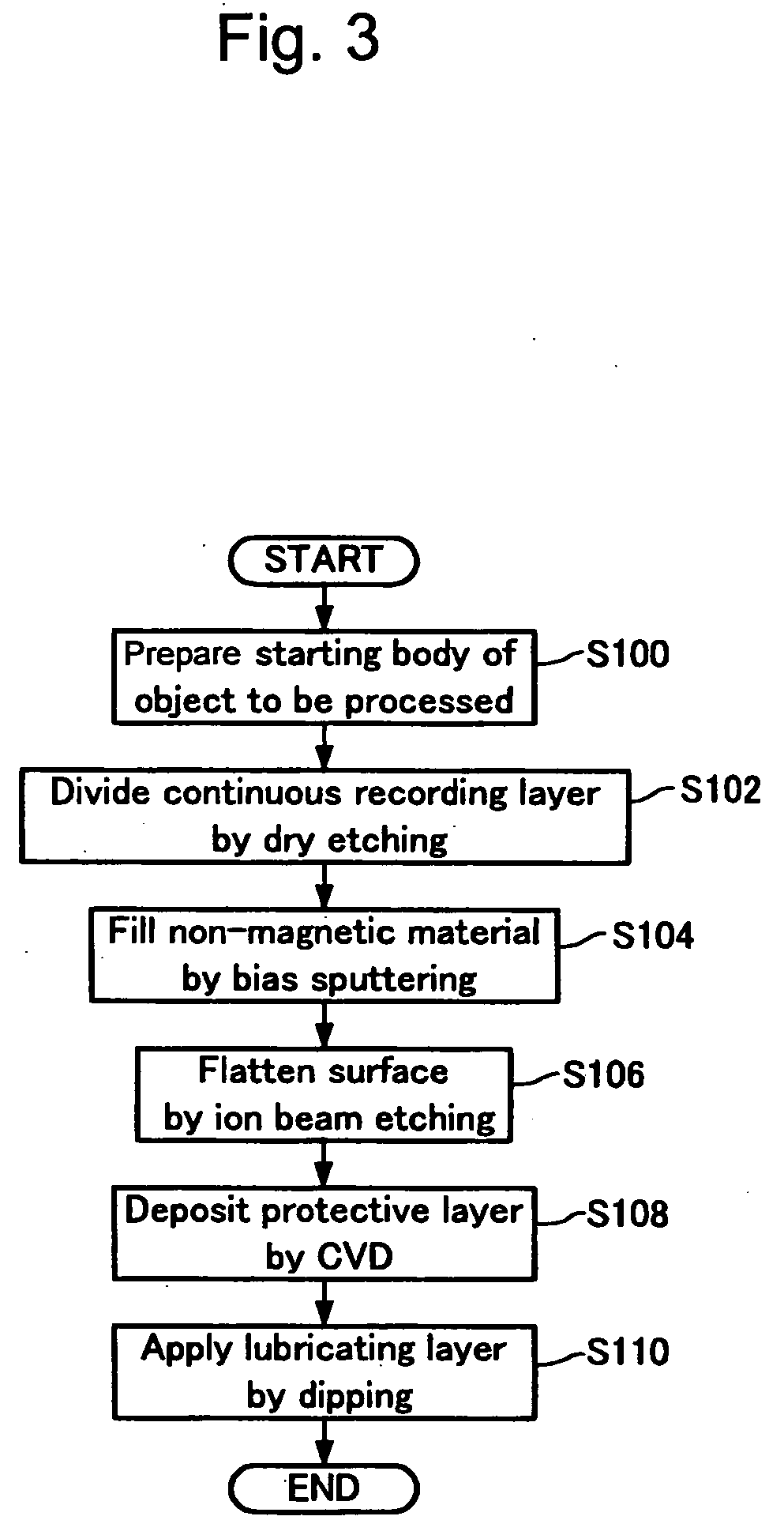
[0096] Then, the non-magnetic material 36 was deposited to a thickness of approximately 40 nm in the non-magnetic material filling step (S104) under the following conditions, to fill the concave portions 34 with the non-magnetic material 36. The thickness of the non-magnetic material described above is the distance between the most projecting portion in the surface of the deposited non-magnetic material 36 and the top face of the recording layer 32.

[0097] Input power: 500 W

[0098] Ar gas pressure: 0.3 Pa

[0099] Bias power: 250 W

[0100] Then, the non-magnetic material 36 above the recording elements 32A was ...

working example 2

[0111] As is described in the foregoing second exemplary embodiment, the gas mixture of Ar gas and C2F6 (ethane hexafluoride) was used as the processing gas for the ion beam etching in the flattening step (S106). The other conditions were same as those of the working example 1. Conditions in the flattening step (S106) were set as follows. Both of the etching rates of the non-magnetic material 36 (SiO2) and the recording element 32A are approximately 260 angstroms / min under the processing conditions according to the working example 2.

[0112] Quantity of flow of Ar+C2F6 gas: 11 sccm

[0113] Ratio of flow of Ar gas in processing gas: approximately 83%

[0114] Gas pressure: 0.05 Pa

[0115] Beam voltage: 500V

[0116] Beam current: 500 mA

[0117] Suppressor voltage: 400V

[0118] Incident angle of ion beam: +90 degrees

[0119] After the flattening step (S106), the surfaces of the recording layer 32 and the non-magnetic material 36 were observed by the AFM, and obtained the following results.

[012...

working example 3

[0129] As is described in the foregoing third exemplary embodiment, the reactive ion etching which used CO gas and NH3 gas as the reactive gas was used in the flattening step (S106), and also the non-magnetic material 36 was made of the composite material of SiO2 and C. The component ratio of the volume of SiO2 in the composite material was approximately 30%. The other steps were the same as those of the working example 1. Conditions in the flattening step (S106) were set as follows. In the processing conditions according to this working example 3, both of the etching rates of the non-magnetic material 36 (SiO2+C) and the recording element 32A are approximately 160 angstroms / min.

[0130] Quantity of flow of CO+NH3 gas: 100 sccm

[0131] Ratio of flow of CO gas in reactive gas: approximately 12.5%

[0132] Gas pressure: 1.0 Pa

[0133] Input power: 1000 W

[0134] Substrate bias power: 5.7 W / cm2

[0135] After the flattening step (S106), the surfaces of the recording layer 32 and the non-magnet...


PUM

PropertyMeasurementUnit
thicknessaaaaaaaaaa
incident angleaaaaaaaaaa

Abstract

A method for manufacturing a magnetic recording medium is provided, by which a magnetic recording medium having a recording layer formed in a concavo-convex pattern, a sufficiently flat surface, and high recording and reproducing precision is efficiently manufactured. In a non-magnetic material filling step, a non-magnetic material is deposited over a recording layer formed in a predetermined concavo-convex pattern over a substrate to fill concave portions of the concavo-convex pattern with the non-magnetic material. In a flattening step, an excess part of the non-magnetic material above the recording layer is removed by dry etching, to flatten surfaces of the recording layer and the non-magnetic material. Processing conditions are set so as to substantially equalize an etching rate of the non-magnetic material with an etching rate of the recording layer with respect to the dry etching in the flattening step.

Description

BACKGROUND OF THE INVENTION [0001] 1. Field of the Invention [0002] The present invention relates to a method for manufacturing a magnetic recording medium in which a recording layer is formed in a concavo-convex pattern. [0003] 2. Description of the Related Art [0004] Conventionally, a magnetic recording medium such as a hard disc has been significantly increased in areal density because of improvement such as fining magnetic particles composing a recording layer, material change, and increased precision in the processing of magnetic heads. Further increase in the areal density is expected in the future. [0005] However, problems such as processing limits of magnetic head, side fringes due to the spread of a magnetic field, and crosstalk have become revealed, so that increase in the areal density by a conventional improvement method has reached its limitation. Thus, the so-called patterned medium type of magnetic recording medium such as a discrete track medium and a discrete bit me...

Claims


Application Information

Patent Timeline
Patent Type & Authority Applications(United States)
IPC IPC(8): G11B5/851G11B5/84G11B5/855H01F1/00H01F41/32
CPCG11B5/851H01F41/32G11B5/855
Inventor HATTORI, KAZUHIROOKAWA, SHUICHISUWA, TAKAHIROHIBI, MIKIHARU
Owner TDK CORPARATION
Why Eureka
Try Eureka