Three-dimensional model

a three-dimensional model and model technology, applied in the field of three-dimensional models, can solve the problems of increasing the cost of producing models, long time-consuming and labor-intensive, and inability to meet the requirements of optical shaping and other laminate shaping methods used in the above-mentioned production method, and achieves the effect of elasticity and flexibility, and shortening the time for laminate shaping

Inactive Publication Date: 2005-08-25
NAGOYA INDUSTRIAL SCIENCE RESEARCH INST
View PDF14 Cites 41 Cited by
  • Summary
  • Abstract
  • Description
  • Claims
  • Application Information

AI Technical Summary

Benefits of technology

[0015] According to this invention, in the step of laminate shaping, since regions such as blood vessels (body cavity model) having relatively small volume are formed, time for laminate shaping can be shortened.
[0016] Furthermore, since a material portion of the three-dimensional model is formed by surrounding the laminate shaped body cavity model by the three-dimensional model molding material, by arbitrarily selecting the three-dimensional model molding material, a three-dimensional model that can satisfy requirements of the medical field can be formed. For example, by using silicone rubber, it is possible to form a cerebral blood vessels model (three-dimensional model) which is transparent and has elasticity and flexibility similar to those of living body.

Problems solved by technology

Consequently, when the present inventors have tried to make a cerebral blood vessels model in accordance with the production method, they have encountered the following problems.
However, any materials used for performing optical shaping and other laminate shaping methods used in the above-mentioned production method cannot satisfy such requirements.
Therefore, much time is needed to laminate shape a cerebral blood vessels model required in the medical field by a conventional production method.
Thus, the cost for producing models is increased, and sometimes the model production cannot respond to an urgent need.

Method used


Image

  • Three-dimensional model
  • Three-dimensional model
  • Three-dimensional model

Examples


first example

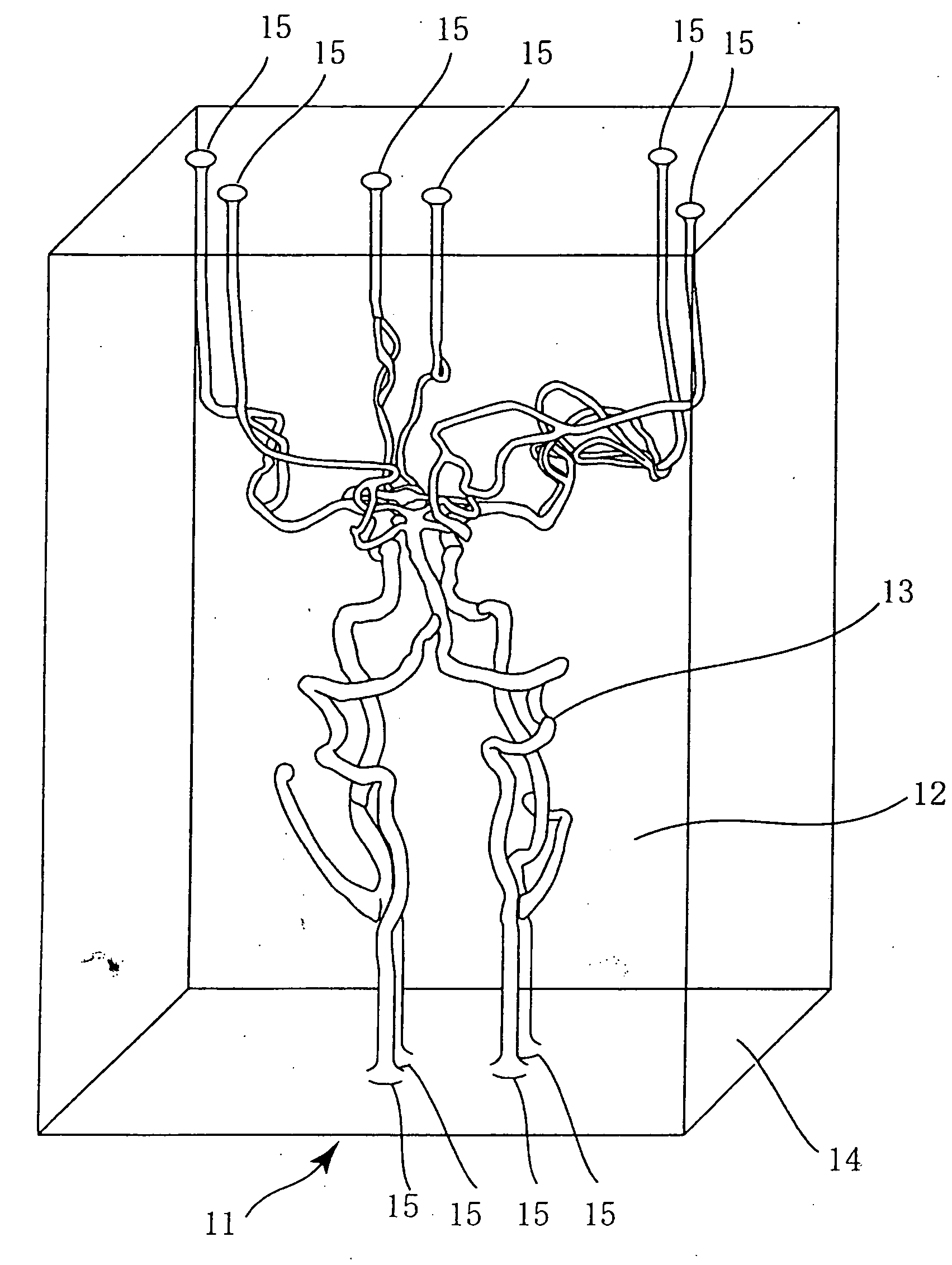
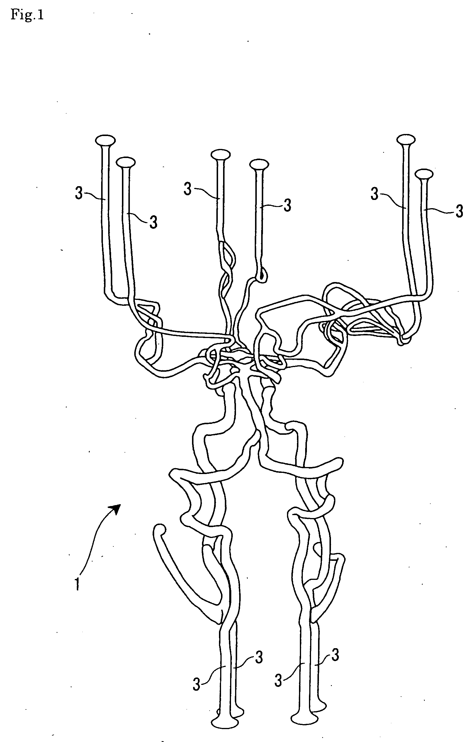
[0105] In order to obtain three-dimensional data regarding the shapes of cerebral blood vessels and affected parts, i.e., cerebral arteries to be targets of a three-dimensional model, a head portion of a patient was imaged with a helical scanning X-ray CT scanner having spatial resolution of 0.35×0.35×0.5 mm while administering contrast media into the blood vessels of the region to be imaged. The three-dimensional data obtained by imaging were reconstructed into 500 pieces of 256-gradation two-dimensional images (tomographic data) having a resolution of 512×512 which were arranged in equal intervals along the body axis so that they are passed to a three-dimensional CAD software, and then image data corresponding to respective two-dimensional images are stored in a 5.25-inch magneto-optical disk by a drive incorporated in the X-ray CT scanner in the order according to the imaging direction.

[0106] Then, by a 5.25-inch magneto-optical drive externally connected to a personal computer,...

second example

[0116] A three-dimensional model 41 of this Example has a spherical shape and has cerebral blood vessel lumens 43 (see FIG. 4). A production method and a molding material of this three-dimensional model 41 is the same as in the First Example except of the shape of the outer mold.

[0117] In the three-dimensional model 41 of this Example, a cubical-shaped sign 45 is embedded inside. On each surface of this sign 45, the direction of a patient's face is described. Since the spherical shaped three-dimensional model 41 is not stable in location, by providing such a sign 45, the orientation of the cerebral blood vessel lumens 43 can be exactly grasped.

[0118] The direction shown by such a sign 45 is specified by computer processing from the location of eyeball and bone tissues extracted from tomogram data. This sign 45 and the body cavity model are simultaneously laminate shaped so that they are arranged in a specific direction. Since this sign 45 is embedded in the three-dimensional model...

third example

[0120]FIG. 6 introduces a medical model 51 of this Example. This medical model 51 includes a spherical shaped three-dimensional model 41 described in Example 2, a case 53 and a translucent fluid 54 filled in the case 53.

[0121] The entire structure of the case 53 is formed of transparent plate (an acrylic plate, etc.). A lid portion 55 located in the upper side is connected to a sidewall with a hinge 56 and can be opened and closed. The translucent fluid 54 is a transparent liquid having the same refractive index as that of the silicone rubber three-dimensional model 41. In this Example, as the translucent fluid 54, silicone oil having an equal refractive index was used. Furthermore, by dissolving a refractive index preparation agent into water, desired translucent fluid can be obtained.

[0122] Since the three-dimensional model 41 has a spherical shape, the entire surface serves as a convex lens, so that cerebral blood vessel cavity inside cannot be visually recognized exactly. When...


PUM

PropertyMeasurementUnit
melting pointaaaaaaaaaa
thicknessaaaaaaaaaa
transparentaaaaaaaaaa

Abstract

A three-dimensional model, wherein coelom models such as blood vessels are stackingly molded based on tomogram data on a subject, the peripheries of the coelom models are surrounded by a three-dimensional model forming material, the three-dimensional model forming material is hardened, and the coelom models are fused or molten and removed, whereby a specified three-dimensional model can be formed.

Description

TECHNICAL FIELD [0001] The present invention relates to a three-dimensional model. More particularly, it relates to a three-dimensional model replicating body cavities such as blood vessels of a subject. BACKGROUND ART [0002] A three-dimensional silicone rubber model replicating cerebral blood vessels is known as University of Geneva Model. This cerebral blood vessels model replicates cerebral blood vessels as cavities in a transparent silicone rubber rectangular parallelepiped, and the cavities are linked to the surface of the model and open at the surface. To this opening, a pump with pulsatile flow is connected and liquid is allowed to flow, whereby it is possible to simulate lesions such as cerebral aneurysm, dural arteriovenous malformation, angiostenosis, etc. in vitro. Furthermore, it is possible to make practices for inserting a catheter or embolus materials into the cerebral blood vessel through the opening. [0003] This cerebral blood vessels model is produced based on dead...

Claims


Application Information

Patent Timeline
Patent Type & Authority Applications(United States)
IPC IPC(8): G09B23/30
CPCG09B23/30
Inventor FUKUDA, TOSHIOARAI, FUMIHITOIKEDA, SEIICHINEGORO, MAKOTO
Owner NAGOYA INDUSTRIAL SCIENCE RESEARCH INST
Why Eureka
Try Eureka