
Arrays and their reading

a technology of arrays and readings, applied in the field of slides, can solve the problems of easy damage, small damage, and easy damage, and achieve the effects of reducing the background signal during array readings, reducing the number of manipulating devices, and reducing the number of manipulating slides

Inactive Publication Date: 2005-08-25
SCHEMBRI CAROL T +1
View PDF4 Cites 4 Cited by
  • Summary
  • Abstract
  • Description
  • Claims
  • Application Information

AI Technical Summary

Benefits of technology

The solution protects the slide from damage, ensures precise positioning for accurate readings, and minimizes background signals, thereby reducing the risk of incorrect results and maintaining the quality of fluorescent signal detection.

Problems solved by technology

First, since the array itself is unprotected it is subject to damage.
Any damage is extremely undesirable for a number of reasons.
For example, slight damage, such as fingerprints or scratches may occur to the sample exposed array which is not noticed.
Such damage could lead to incorrect readings with serious consequences in interpretation of results.
Also, it is not uncommon for the slides to be broken during insertion or removal from these scanners.
Slide glass is easily chipped or broken.
Losing a slide at this stage of the experiment can be extremely costly.
Typically, the arrayed slides cost several hundred dollars and may involve long lead times. The samples under test may be from tumors or other hard-to-obtain sources.
The fluorescent dyes typically employed are currently quite expensive.
Therefore, a broken slide represents the loss of many hundreds of dollars and many hours of work.
However, the present invention further realizes that precision placement usually involves firm surfaces and forcibly clamping the slides, which actions can result in slide breakage or array damage.
If the slide is simply placed into a chamber to avoid clamping, large positional tolerances are needed which reduce the detection quality of the signals from the surface.

Method used


Image

  • Arrays and their reading
  • Arrays and their reading
  • Arrays and their reading

Examples


Embodiment Construction

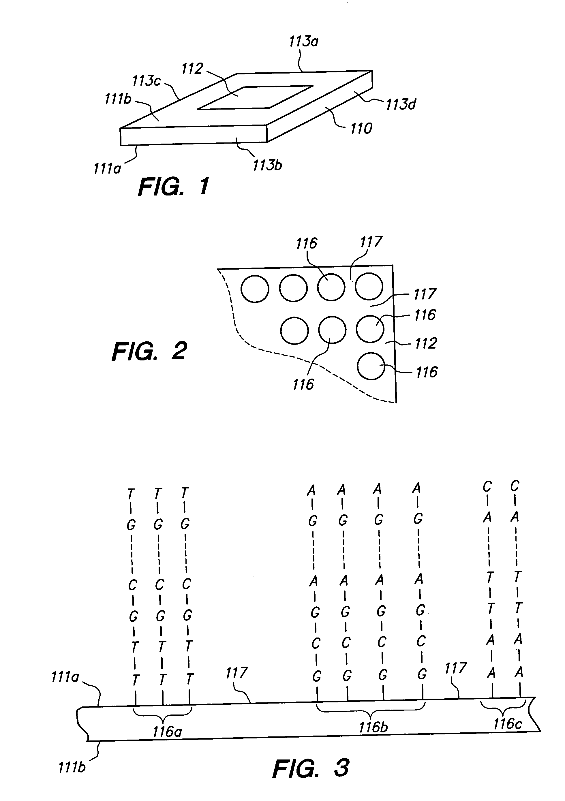
[0032] In the present application, unless a contrary intention appears, the following terms refer to the indicated characteristics. A “biopolymer” is a polymer of one or more types of repeating units. Biopolymers are typically found in biological systems (although they may be made synthetically) and particularly include peptides or polynucleotides, as well as such compounds composed of or containing amino acid analogs or non-amino acid groups, or nucleotide analogs or non-nucleotide groups. This includes polynucleotides in which the conventional backbone has been replaced with a non-naturally occurring or synthetic backbone, and nucleic acids (or synthetic or naturally occurring analogs) in which one or more of the conventional bases has been replaced with a group (natural or synthetic) capable of participating in Watson-Crick type hydrogen bonding interactions. Polynucleotides include single or multiple stranded configurations, where one or more of the strands may or may not be com...


PUM

PropertyMeasurementUnit
sizeaaaaaaaaaa
areaaaaaaaaaaa
areaaaaaaaaaaa

Abstract

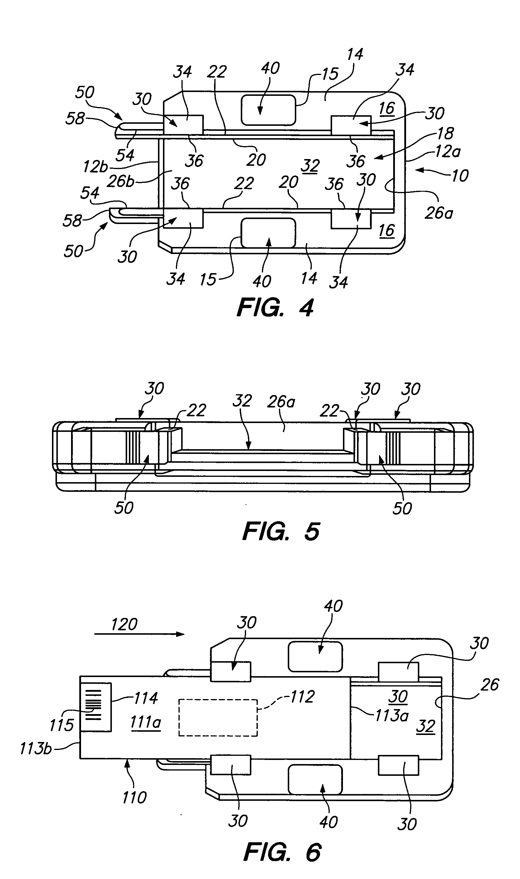
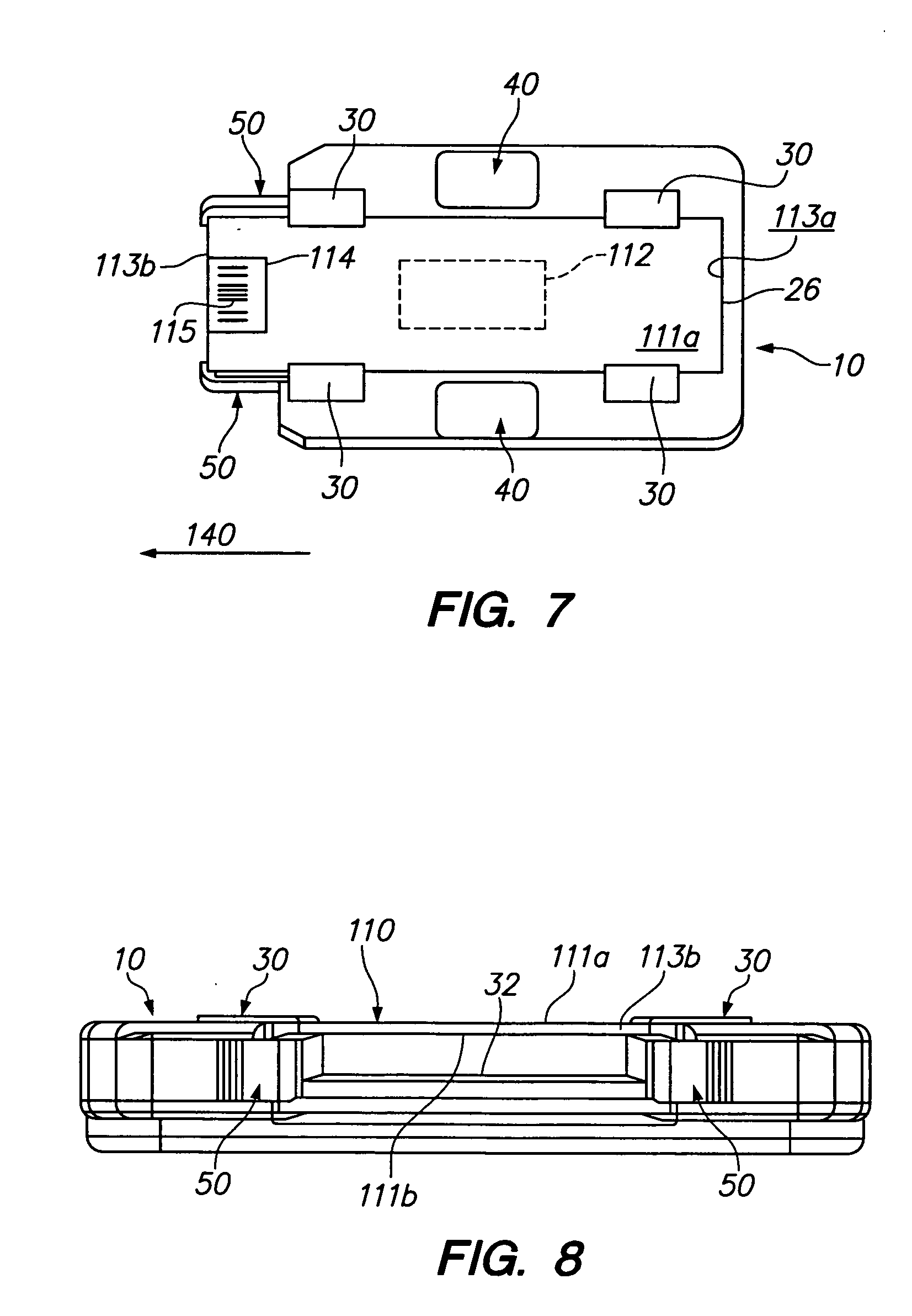
A method of reading an array of moieties such as polynucleotides (for example, DNA) on at least a portion of a surface of a transparent slide which is opposite a first portion on the opposing surface, which array has been previously exposed to a sample. The method may include mounting the slide on a slide holder and retaining the slide thereon in a mounted position in which the holder does not contact the previously exposed array. The holder is then inserted into an array reader and the array read. A holder and slides which can be used in the method are also provided.

Description

[0001] This application claims priority to copending application Ser. No. 09 / 671,966, filed Sep. 27, 2000, under 35 U.S.C. 120, the entirety of which is incorporated herein by reference.FIELD OF THE INVENTION [0002] This invention relates to slides holding multiple moieties to be read, and in particular to arrays such as polynucleotide arrays (for example, DNA arrays), which are useful in diagnostic, screening, gene expression analysis, and other applications. BACKGROUND OF THE INVENTION [0003] Polynucleotide arrays (such as DNA or RNA arrays), are known and are used, for example, as diagnostic or screening tools. Such arrays include regions of usually different sequence polynucleotides arranged in a predetermined configuration on a substrate. These regions (sometimes referenced as “features”) are positioned at respective locations (“addresses”) on the substrate. In use, the arrays, when exposed to a sample, will exhibit an observed binding or hybridization pattern. This binding pat...

Claims


Application Information

Patent Timeline
Patent Type & Authority Applications(United States)
IPC IPC(8): B01L9/00C12M1/34C12Q1/68G01N21/01G01N33/48G01N33/50G06F19/00
CPCB01L9/52Y10T436/112499B01L2300/0822B01L2300/0819
Inventor SCHEMBRI, CAROL T.TAM, KIMBERLY L.
Owner SCHEMBRI CAROL T
Learn More