Method of detecting error spot in DNA chip and system using the method

a technology of error spot and dna chip, applied in the field of method of detecting error spot and system, can solve the problems of limiting the possibility of identifying sick people and reducing the reliability of analysis, and achieve the effect of increasing the reliability of statistical analysis

Inactive Publication Date: 2005-08-25
SAMSUNG ELECTRONICS CO LTD
View PDF5 Cites 13 Cited by
  • Summary
  • Abstract
  • Description
  • Claims
  • Application Information

AI Technical Summary

Benefits of technology

[0014] The present invention provides a method of detecting an error spot, which increases a reliability in a statistical analysis by detecting the error spot in a DNA chip and excluding the detected error spot in the statistical analysis and a system using the method.
[0015] The present invention also provides a computer-readable recording medium having recorded therein a computer program for executing in a computer a method of detecting an error spot, the method increasing a reliability in a statistical analysis by detecting the error spot in a DNA chip and excluding the detected error spot in the statistical analysis.

Problems solved by technology

If the quantification operation is performed based on false information due to the errors and the statistical analysis is performed using the quantified false data, the false spot data may reduce a reliability of the analysis and limit the possibility to identify a sick person.

Method used


Image

  • Method of detecting error spot in DNA chip and system using the method
  • Method of detecting error spot in DNA chip and system using the method
  • Method of detecting error spot in DNA chip and system using the method

Examples


Embodiment Construction

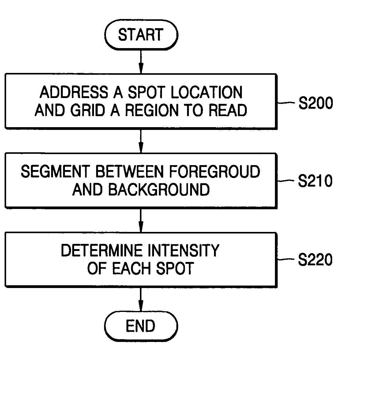
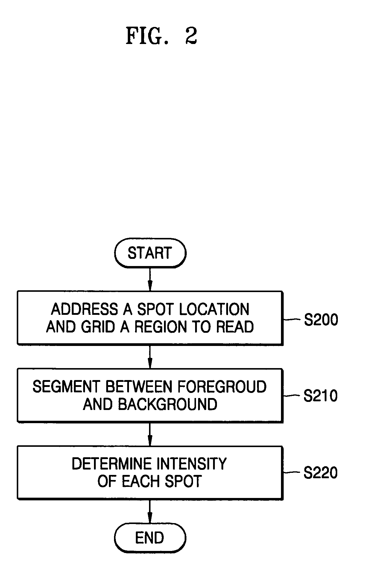
[0032]FIG. 2 is a flowchart illustrating an image processing procedure for a DNA chip and FIG. 3 is a diagram illustrating an image scanning of a DNA chip.

[0033] In general, the image processing procedure of a DNA chip includes a scanning operation and a quantification operation. The scanning operation and the quantification operation are closely related to each other. Values obtained from the quantification operation change depending on a scanning method.

[0034] Referring to FIGS. 2 and 3, there is first performed addressing of a location and a shape of each spot in the DNA chip and gridding of a region to be read (operation (S200)).

[0035] Next, a segmentation is performed (operation (210)) in which pixels belonging to a background region (310) and pixels belonging to a foreground region (320) in the addressed spot are segmented. Various methods have been proposed to segment the foreground (320) and the background (310). Representative methods include a fixed circle assumption an...


PUM

PropertyMeasurementUnit
degrees of freedomaaaaaaaaaa
densityaaaaaaaaaa
shapeaaaaaaaaaa

Abstract

Provided are a method of detecting an error spot and a system using the method. The method includes analyzing a difference in variances of a background intensity and a foreground intensity for each spot in a DNA chip, verifying whether the mean of the background intensity and the mean of the foreground intensity are significantly different from each other based on the difference in variances, and judging an error spot based on the results of the verifying operation. Thus, the reliability in statistical analysis can be increased by excluding the error spot in the statistical analysis.

Description

BACKGROUND OF THE INVENTION [0001] This application claims the benefit of Korean Patent Application No. 10-2004-0011654, filed on Feb. 21, 2004, in the Korean Intellectual Property Office, the disclosure of which is incorporated herein in its entirety by reference. [0002] 1. Field of the Invention [0003] The present invention relates to a method of detecting an error spot and a system using the method, and more specifically, to a method of detecting an error spot by quantifying DNA chips and a system using the method. [0004] 2. Description of the Related Art [0005] DNA chips have been manufactured using molecular biological technologies and newly developed mechanical and electronic engineering technologies. DNA chips are chips in which several hundreds to several hundreds of thousands DNAs are integrated in a very small space using mechanical automation and electronic control technologies. That is, DNA chips are chips to which many types of DNAs are attached with high density for de...

Claims


Application Information

Patent Timeline
Patent Type & Authority Applications(United States)
IPC IPC(8): G01N33/53G16B25/00C12N15/09C12Q1/68G01N37/00G06F19/00
CPCG06F19/20G16B25/00B22D17/203B22D17/2007
Inventor OH, JI-YOUNG
Owner SAMSUNG ELECTRONICS CO LTD
Why Eureka
Try Eureka