Method of recapturing a stent
a technology of endoluminal devices and stents, applied in the field of endoluminal devices, can solve the problems of catastrophic failure of balloons containing radioactive or cryogenic fluids, balloon failure, etc., and achieve the effect of being ready to withdraw
- Summary
- Abstract
- Description
- Claims
- Application Information
AI Technical Summary
Benefits of technology
Problems solved by technology
Method used
Image
Examples
second embodiment
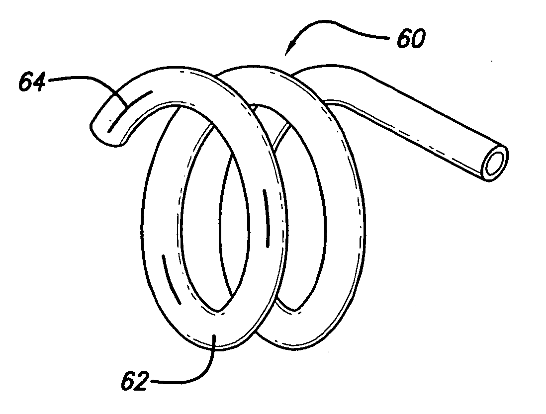
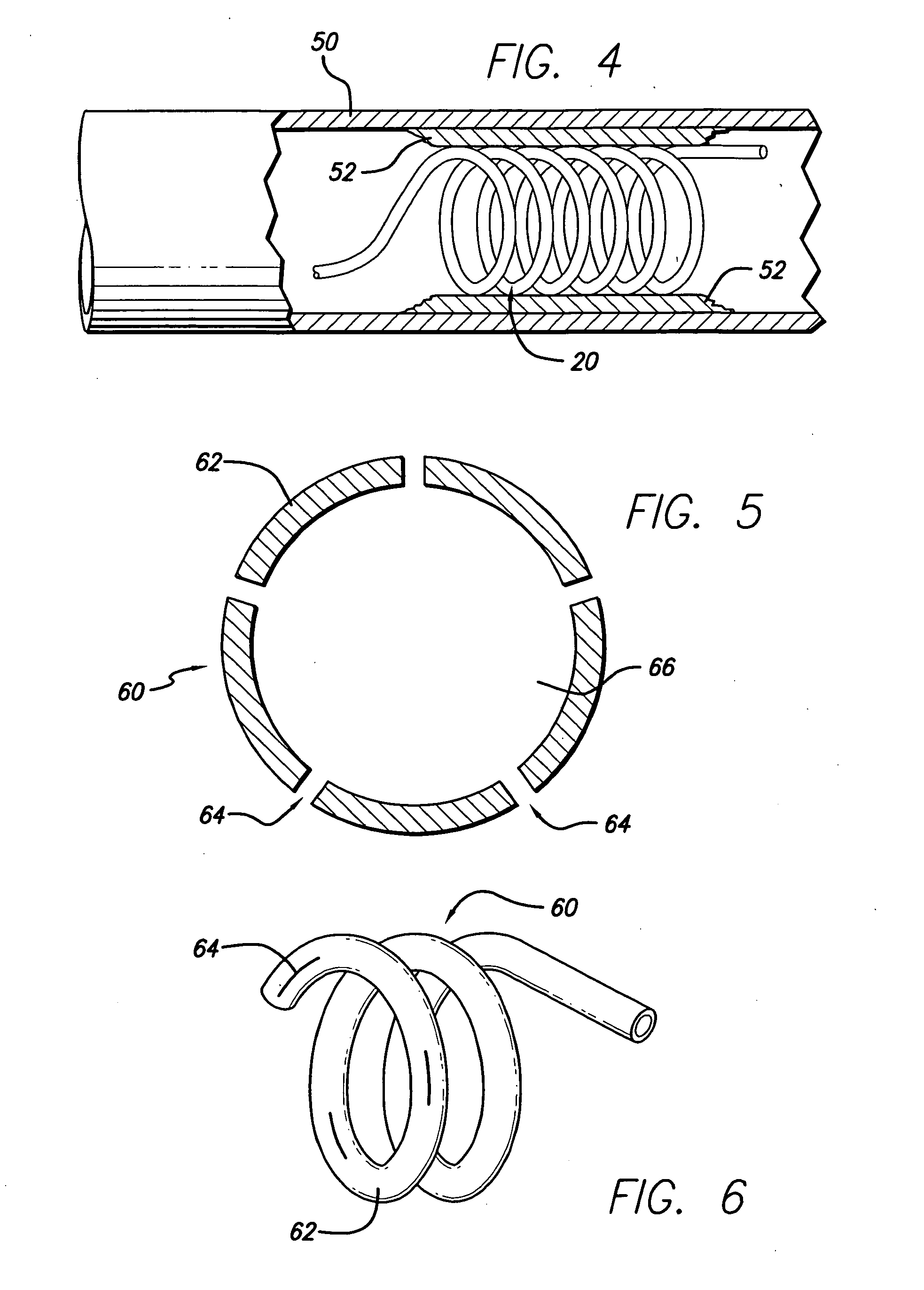
[0036]FIG. 5 depicts the invention. In this embodiment, the hollow stent 60 has only one fluid pathway 66, an inlet without an outlet, and is used to deliver drugs to affected areas. Once the stent 60 is inserted into place and is in its enlarged configuration, drugs are delivered through the catheter to the stent 60. Stent 60 can be constructed in various ways to facilitate the delivery of drugs. In one case, as shown in FIG. 6, the stent 60 is constructed with regions or segments that have pores 64 to allow drug seepage from the tubing 62. Alternatively, continuously porous metal, porous plastic, or a combination of metal and plastic can be used. The perforations 64 or slits in the stent to facilitate drug delivery must be of sufficiently small size to allow the passage of the drug through the entire length of the stent so that all areas can be treated. It will be apparent that pore size can control the rate at which the drug is dispensed. It is possible to cover the pores 64 with...
third embodiment
[0037] the invention, FIG. 7, has a hollow stent 70 containing a single fluid pathway. The tubing 72 can be made of any of the materials discussed above, but in this embodiment, the stent 70 has an inlet path 78 that carries the fluid to the distal end 74 of stent 70 where it then runs through the coils. In this embodiment, a valve 80 connects the stent 70 to catheter 30. FIG. 8 shows a cross-sectional view of valve 80. The pressure from the liquid sent through the catheter causes the gate 82 of valve 80 to open to allow the fluid into the inlet path 78. The pressure that forces the opening of gate 82 causes the simultaneous opening of gate 84, allowing the fluid that is circulated through the stent 70 to exit through pathway 36 of catheter 30. The fluid entering and exiting through catheter 30 must also go through a check ball valve assembly similar to the one shown in FIG. 2. Again, flaps or other “one way” valve mechanisms can be applied. After all incoming fluid has been deliver...
fourth embodiment
[0038] In a fourth embodiment, a hollow coiled stent 90 is formed from polytetrafluoroethylene (PTFE) 92. In FIG. 9, a perspective view of this embodiment can be seen. The stent 90 consists of a support wire 94 over which PTFE 92 is fitted. The pliable structure resulting is then formed into a coiled stent. The PTFE 92 is fitted around the wire 94 so that there is sufficient room to allow the passage of fluid. FIG. 10 shows a cross-sectional view of stent 90, illustrating the pathway 96 created around the support wire 94 to allow the passage of fluid. In this embodiment, stretched expanded PTFE can be used to create a porous stent to facilitate the delivery of drugs. The wire 94 can also be hollow (passageway 95) so that the stent 90 can simultaneously deliver drugs and radioactive fluid or temperature regulating fluid.
PUM
 Abstract
Description
Claims
Application Information
 - R&D
- Intellectual Property
- Life Sciences
- Materials
- Tech Scout
- Unparalleled Data Quality
- Higher Quality Content
- 60% Fewer Hallucinations
Browse by: Latest US Patents, China's latest patents, Technical Efficacy Thesaurus, Application Domain, Technology Topic, Popular Technical Reports.
© 2025 PatSnap. All rights reserved.Legal|Privacy policy|Modern Slavery Act Transparency Statement|Sitemap|About US| Contact US: help@patsnap.com


