Deceleration control apparatus and method for a vehicle

a control apparatus and vehicle technology, applied in vehicle position/course/altitude control, braking system, instruments, etc., can solve the problems of riding discomfort, and inability to apply the optimum deceleration to the vehicl

Inactive Publication Date: 2005-08-25
TOYOTA JIDOSHA KK
View PDF19 Cites 55 Cited by
  • Summary
  • Abstract
  • Description
  • Claims
  • Application Information

AI Technical Summary

Benefits of technology

[0015] Also, with the deceleration control apparatus and method for a vehicle described above, it is particularly easy to set a speed change amount that takes into consideration the balance between the deceleration force (when going into a curve) and the acceleration force (when coming out of a curve). When going into a curve, a braking force which is a combination of the braking force by the brake system and a speed suitable for after the vehicle has entered the curve can be generated, such that suitable vehicle driving characteristics going into the curve, as well as after the vehicle has entered the curve, can be obtained. The spee

Problems solved by technology

When shift point control is performed in a stepped automatic transmission in order to apply a predetermined deceleration to the vehicle according to the size of the corner, it may not be possible to apply the optimum deceleration to the vehicle.
As

Method used


Image

  • Deceleration control apparatus and method for a vehicle
  • Deceleration control apparatus and method for a vehicle
  • Deceleration control apparatus and method for a vehicle

Examples


Embodiment Construction

[0028] In the following description and the accompanying drawings, the present invention will be described in more detail with reference to exemplary embodiments.

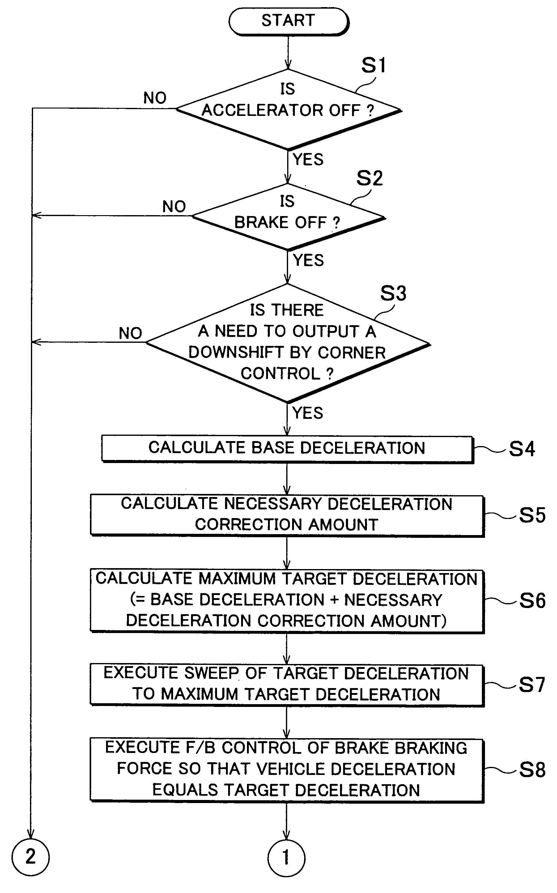
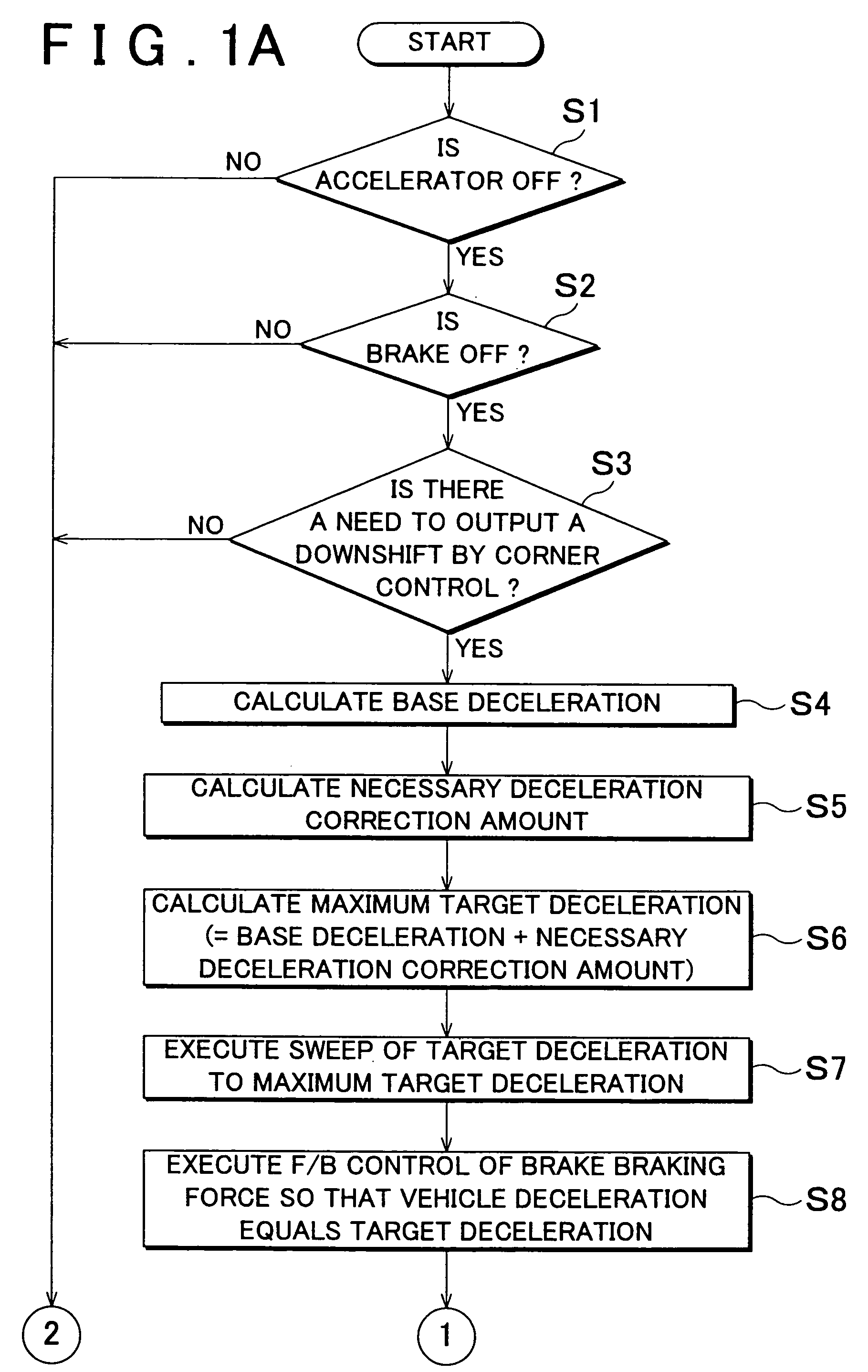
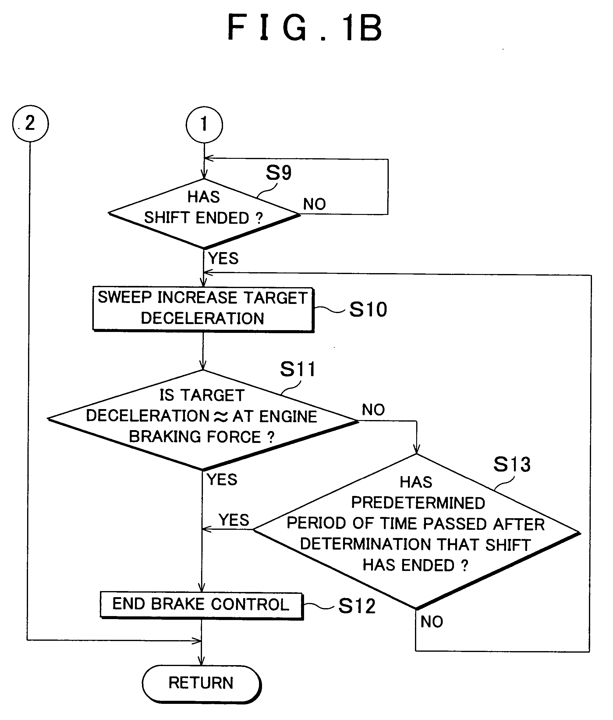
[0029] One exemplary embodiment will now be described with reference to FIGS. 1 to 11. This exemplary embodiment relates to a deceleration control apparatus for a vehicle that performs cooperative control of a brake (i.e., a brake system) and an automatic transmission.

[0030] In this exemplary embodiment, when shift point control (which selects the optimum speed based on, for example, the curvature radius of an upcoming corner) is performed by cooperative control of a stepped automatic transmission and the brakes, the optimum deceleration characteristics are able to be achieved by adding the deceleration determined based on a parameter that is determined by the vehicle speed, the curvature radius of the corner, and the required timing of the deceleration, to the deceleration by a downshift of the automatic transmission (AT...


PUM


Abstract

A deceleration control apparatus and method for a vehicle, which performs deceleration control on the vehicle by an operation of a brake system which applies a braking force to the vehicle and a shift operation which shifts a transmission of the vehicle into a relatively low speed or speed ratio, performs the shift operation and the operation of the brake system such that a target deceleration set based on a curvature or curvature radius of a curve in a road ahead of the vehicle, a distance to the curve, and a vehicle speed, acts on the vehicle. As a result, a desired deceleration according to the distance to the curve is able to be applied to the vehicle.

Description

INCORPORATION BY REFERENCE [0001] The disclosure of Japanese Patent Application No. 2004-033390 filed on Feb. 10, 2004 including the specification, drawings and abstract is incorporated herein by reference in its entirety. BACKGROUND OF THE INVENTION [0002] 1. Field of the Invention [0003] The invention relates to a deceleration control apparatus and method for a vehicle. More particularly, the invention relates to a deceleration control apparatus and method for a vehicle, which controls deceleration of the vehicle by an operation of a brake system which applies braking force to the vehicle and a shift operation that shifts an automatic transmission into a relatively low speed. [0004] 2. Description of the Related Art [0005] JP(A) 10-132072 discloses technology which detects the current position of a vehicle and an upcoming curve, searches for a recommended speed that will enable the vehicle to travel smoothly through the upcoming curve, and decelerates the vehicle to the recommende...

Claims


Application Information

Patent Timeline
IPC IPC(8): B60T8/00B60T7/12F16H59/44F16H59/66F16H61/02F16H61/18F16H61/21F16H61/68F16H61/684F16H61/686F16H63/48G06F7/70
CPCB60K41/262B60K2741/265B60T2210/24B60T2260/04B60W10/115Y10T477/621B60W30/18109B60W2520/10B60W2550/143B60W2720/106B60W2720/125B60W10/184B60W2552/20B60W2552/30B60W10/18F16H61/21B60W30/08B60W40/076
Inventor SHIIBA, KAZUYUKIIWATSUKI, KUNIHIRO
Owner TOYOTA JIDOSHA KK
Why Eureka
Try Eureka