Method and machine for manufacturing energy accumulating components, and components made thereby

a technology of energy accumulating components and manufacturing methods, applied in the direction of fuel cells, primary cells, secondary cells, etc., can solve the problems of limited flexibility of components in occupying the various geometric requirements of end users, and achieve the effect of maximizing the saturation of volumes available and minimizing material was

Inactive Publication Date: 2005-09-01
KEMET ELECTRONICS CORP
View PDF7 Cites 12 Cited by
  • Summary
  • Abstract
  • Description
  • Claims
  • Application Information

AI Technical Summary

Benefits of technology

[0009] The aim of the present invention is to obviate the cited drawbacks and meet the mentioned requirements, by providing a method for manufacturing electrical components of the energy-accumulating electrostatic or electrochemical type, capable of having even hig

Problems solved by technology

Thermomechanical stabilization, deposition of the metallic layer to which the terminals for feeding current will be connected, and impregnation in a resin lead to the finished product.
The resulting component has limited flexibility in occupying the various geometric requirements of the end user (particularly in the case of production of cylindrical components) and in saturating the volume available for installation of the component (the available spaces are generally polygonal and almost never circular).
The critical points of

Method used


Image

  • Method and machine for manufacturing energy accumulating components, and components made thereby
  • Method and machine for manufacturing energy accumulating components, and components made thereby
  • Method and machine for manufacturing energy accumulating components, and components made thereby

Examples


Embodiment Construction

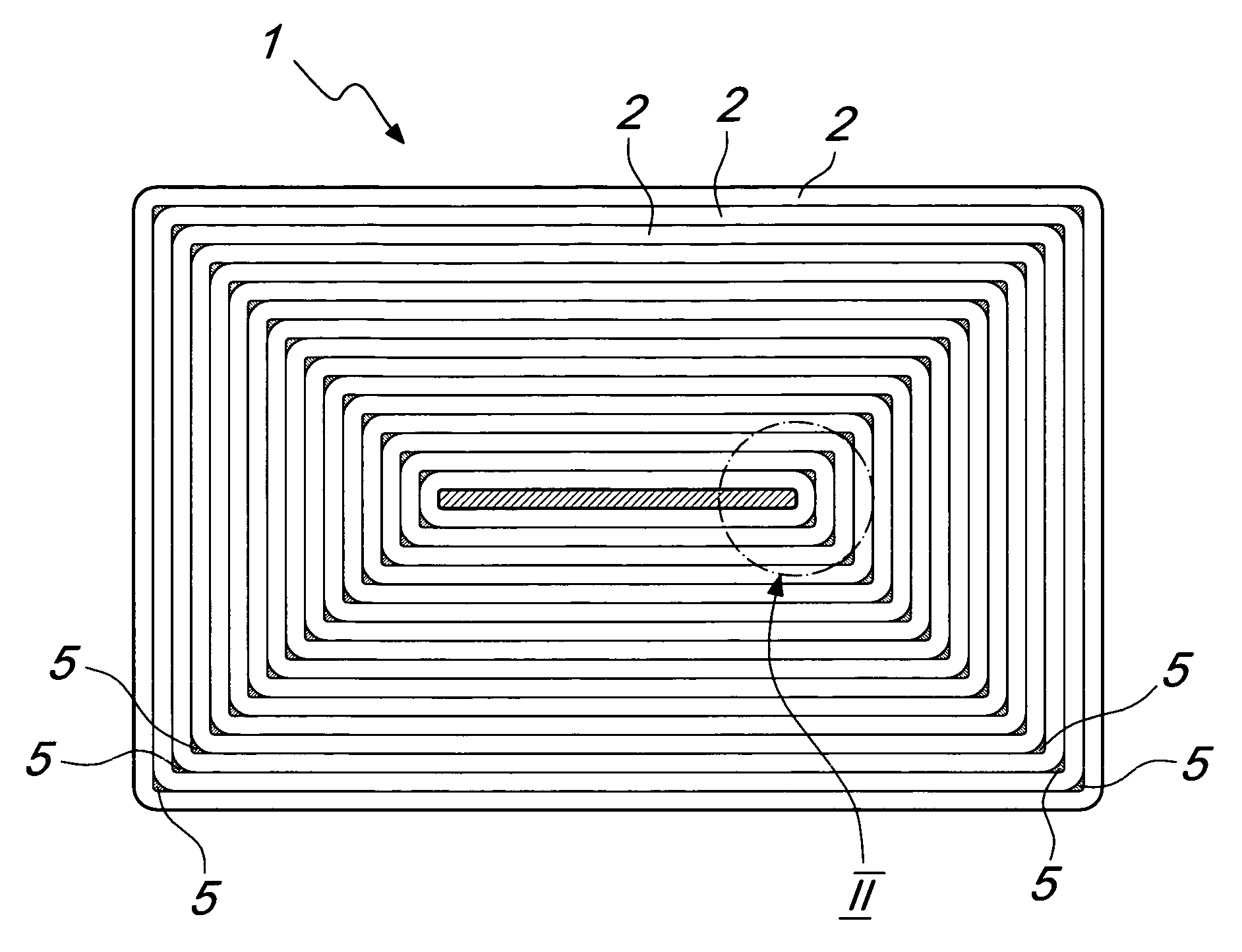
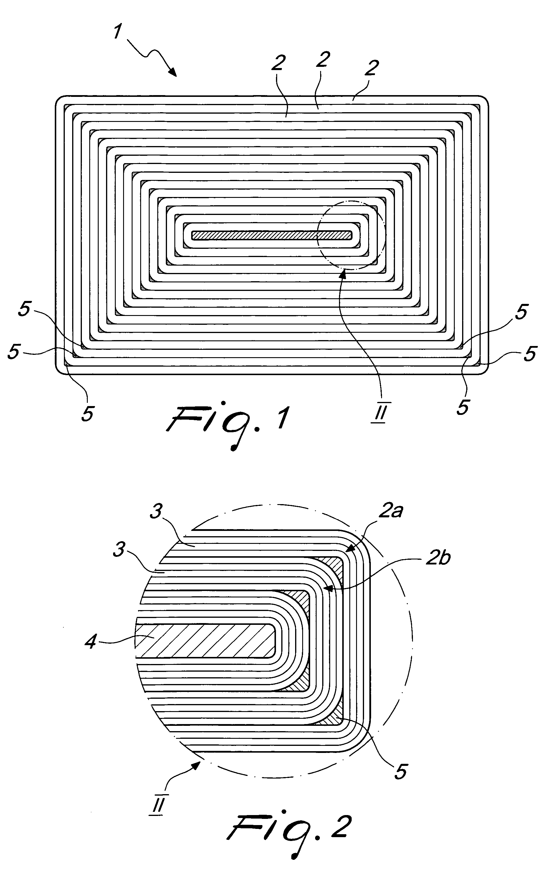
[0039] With reference to the figures, the reference numeral 1 generally designates a capacitor provided according to the method.

[0040] The capacitor 1 is constituted by a plurality of layers 2 of film 3 made of a material such as plastics, provided with a metallized surface and wound onto a support 4, each outer layer 2a being separated from the inner layer 2b (at the corners) by means of respective spacers 5.

[0041] The support 4 and spacers 5 can be made of any suitable material, such as known electrically nonconducting materials.

[0042] The support 4 can have any shape, provided that in plan view none of its internal angles exceeds 180° (for example, a star-shaped support cannot be used).

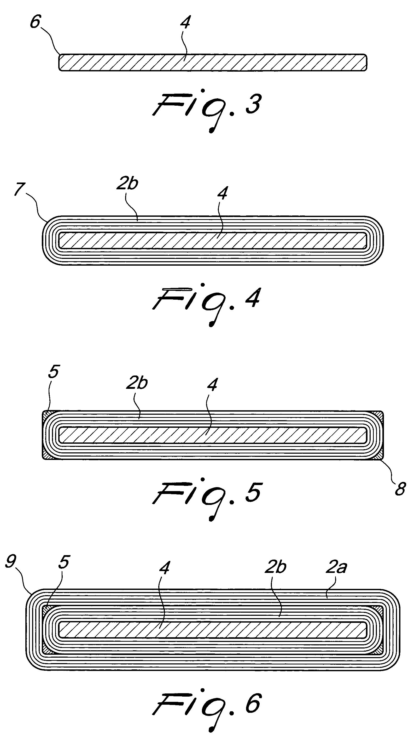
[0043] Its corners have a radiusing provided by a radius of curvature 6 that is preferably set to 1 mm (different radii of curvature, greater or smaller than this one even by a few orders of magnitude, can be preferred in other applications).

[0044] The film 3 is wound onto the support 4 until ...


PUM

PropertyMeasurementUnit
Thicknessaaaaaaaaaa
Thicknessaaaaaaaaaa
Angleaaaaaaaaaa

Abstract

A method for manufacturing electrical components of the energy-accumulating electrostatic or electrochemical type, consisting in winding at least two layers of a film on a support made of an electrically nonconducting material that has a substantially polygonal cross-section, by providing a preset number of film turns until a predefined thickness is reached, and forming a first layer; arranging respective spacers at the corners of the polygon in which the contour of the wound film is inscribed; and winding more turns of film around the first layer and around the spacers inserted at the corners, to form a second layer. A machine by means of which the method is performed comprises a rotatingly mounted frame on which the support is fixed for winding of the layer of film.

Description

BACKGROUND OF THE INVENTION [0001] The present invention relates to a method for manufacturing electrical components of the energy-accumulating electrostatic or electrochemical type (such as for example plastic film capacitors, double-layer capacitors, supercapacitors and primary and secondary batteries), to the machine that performs the method, and to the components provided according to the method (for example with said machine). [0002] The current method of providing film-type capacitors made of a metallized material such as plastics (hereinafter termed simply “metallized plastic film”, that is assumed to include all of the films made of polymeric materials or with natural rubbers having at least one surface coated with an electrically conducting material) entails a first winding step, during which two or more superimposed plastic films are wound onto a support (having variable shapes and dimensions depending on the geometric and electrical characteristics of the capacitor to be ...

Claims


Application Information

Patent Timeline
IPC IPC(8): H01G9/02H01G4/32H01G9/00H01G9/15H01G9/22H01G11/02H01G11/04H01G11/06H01G11/14H01G11/20H01G11/26H01G11/52H01G11/56H01G11/66H01G11/74H01G11/78H01G11/84H01G11/86H01G13/02H01M4/66H01M6/16H01M10/04H01M10/05H01M10/052H01M10/0525H01M10/0565H01M10/0587H01M10/36
CPCH01G9/151Y10T29/49108H01G9/22H01G11/04H01G11/06H01G11/26H01G11/56H01G13/02H01M10/0409H01M10/0431H01M10/052H01M10/0525H01M10/0565H01M10/0587Y02E60/13Y02E60/122Y10T29/53135H01G9/155Y02E60/10Y02P70/50H01G11/82
Inventor RIGHI, SAUROMAZZA, MIRKO
Owner KEMET ELECTRONICS CORP
Why Eureka
Try Eureka