Riving knife assembly for a dual bevel table saw

a technology of dual bevels and assembly parts, which is applied in the field of table saws, can solve the problems of many beveling assemblies included with table saw assembly, limited beveling capabilities, and unwanted contact, and achieve the effect of maximizing the functional capability of the saw, promoting ease of use, and full cutting capability

Active Publication Date: 2005-09-01
BLACK & DECKER INC
View PDF99 Cites 72 Cited by
  • Summary
  • Abstract
  • Description
  • Claims
  • Application Information

AI Technical Summary

Benefits of technology

[0010] Accordingly, the present invention is directed to a dual bevel table saw including a saw blade operationally coupled with a bi-directional beveling assembly for promoting ease of use while maximizing the functional capability of the saw. Thus, the saw blade is enabled to provide a full depth of cut capability even when disposed at various angles relative to a support surface (table) of the dual bevel table saw. Further, the beveling assembly, regardless of the direction of angular adjustment of the saw blade, enables the positioning of a motor, coupled with the saw blade, in a manner promoting the full range of angular adjustment of the saw blade, with the motor free from contacting with other components of the table saw, such as the underside of the table or other components. Thus, the present invention promotes the angular adjustment of the saw blade through positioning capabilities of the motor.
[0011] Another object of the present invention is to prevent contact between a mounting assembly, that operationally couples the saw blade with the table saw, and the table or other structural components of the table saw. It is a further object of the present invention to provide a table saw assembly capable of maintaining an appropriate tension on an apparatus for transferring the driving force of the motor to the saw blade for imparting angular momentum to the saw blade.
[0012] It is a still further object of the present invention to provide a mounting assembly, for promoting bi-directional angular adjustment capabilities of the beveling assembly by enabling the re-positioning of the saw blade. It may be further seen, in the present invention, that other components, such as the table or support structure(s), may include additional features which promote the ease of use and functional capabilities of the dual bevel table saw. For example, the table may include a throat assembly, operationally engaged by the saw blade, which advantageously enables the re-positioning of the saw blade to promote the angular adjustment capabilities of the present invention.
[0013] Additionally, the present invention is further directed to providing features which enable the dual bevel table saw with multiple functionalities. The functionalities may include measurement systems, dust collection systems, non contact power tool control systems, and the like, which in operational concert with the bi-directional beveling assembly providing significant advantage.

Problems solved by technology

Unfortunately, many beveling assemblies included with table saw assemblies, and the like, are limited in the capabilities they may provide to the operator.
A typical limitation of many beveling assemblies is the enablement of beveling in a single tilt orientation.
Other beveling assemblies have limited beveling capabilities resulting from unwanted contact between the component features of the saw assembly or beveling assembly and other structural impediments of the table saw assembly, such as the unwanted contact between the motor, which drives the saw blade of the table saw assembly, and the underside of the planar surface of the table or structural support features of the table saw assembly.
Additionally, unwanted contact may result from contact between the mounting assembly of the saw blade and the table.
Unfortunately, attempts to resolve these problems have resulted in assemblies which may require a user to accept limited capabilities.
For example, unwanted contact is decreased, but only by limiting the depth of cut capabilities of the saw blade of the table saw assembly.
Additional limitations may be a result of design limitations.
Such a situation may result in decreased performance of the saw assembly during beveling due to changes in tolerances resulting from changes in the positions of these features due to beveling.
Another design limitation is the typical arbor assembly is enabled as a single axle, which may be limited to coupling with the saw blade to impart angular momentum on a single end of the axle.
This may result in the beveling assembly enabled with the single axle arbor assembly limiting its capabilities to a single tilt orientation, as described previously.
Still further, this may result in increased time spent attempting to properly re-align the single axle arbor assembly when transitioning between beveling in a first tilt orientation to beveling in a second tilt orientation, such as from right to left.
This may significantly decrease productivity accomplished through use of the table saw employing such a single axle arbor assembly.
Further, due to such drastic re-positioning required by the single axle arbor assembly there may be an increase in tolerance misalignments resulting in increases in non-production time spent by the power tool.
Unfortunately, after the truing of the arbor assembly is complete the parts of the arbor assembly, such as the bearing for example, may wear out due to use, requiring replacement.

Method used


Image

  • Riving knife assembly for a dual bevel table saw
  • Riving knife assembly for a dual bevel table saw
  • Riving knife assembly for a dual bevel table saw

Examples


Embodiment Construction

[0054] Reference will now be made in detail to the presently preferred embodiments of the invention, examples of which are illustrated in the accompanying drawings.

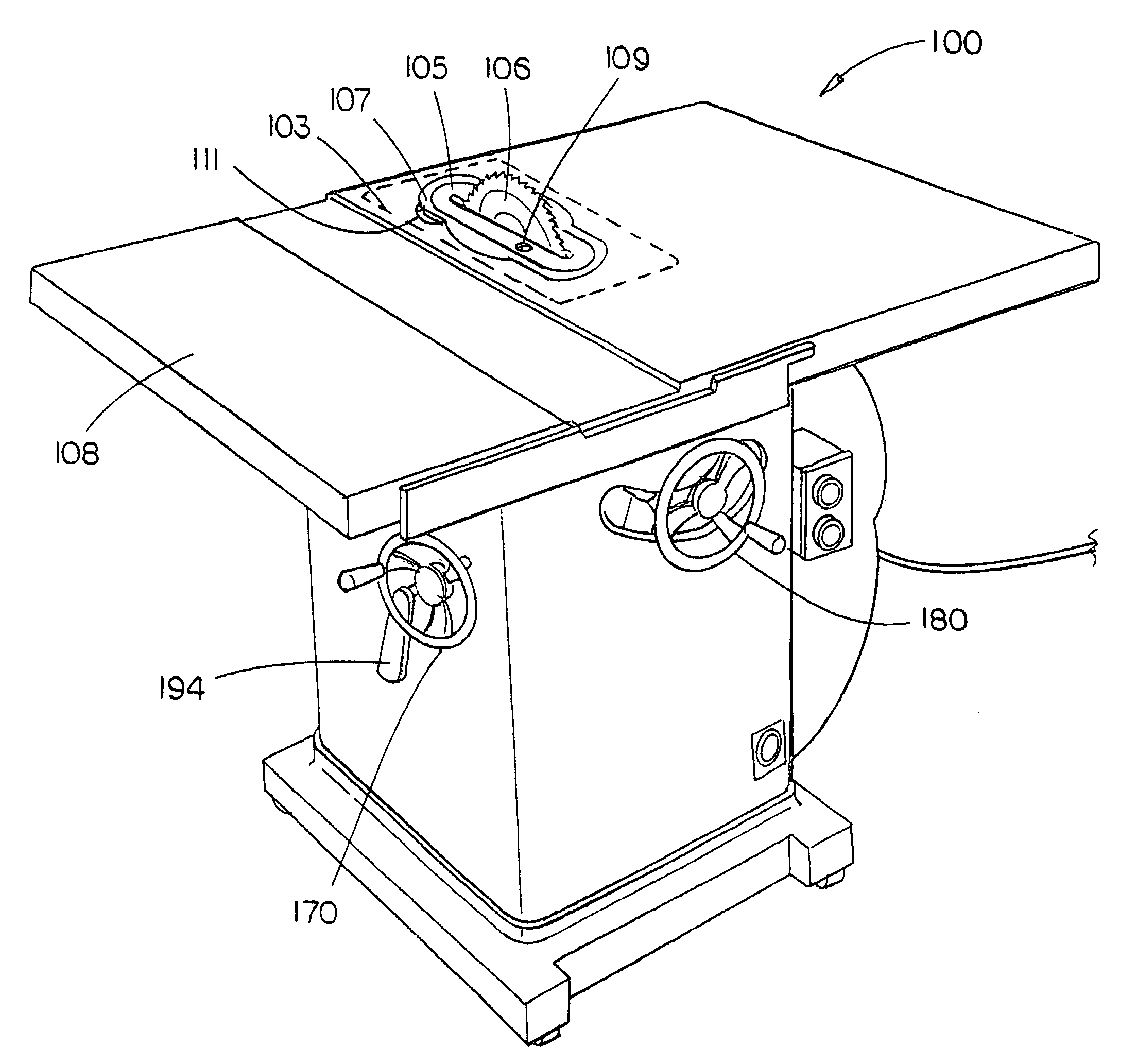
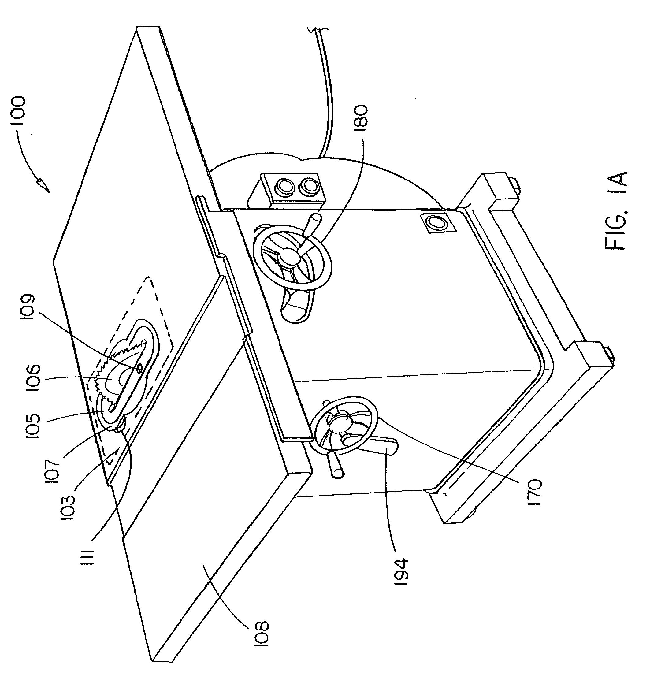
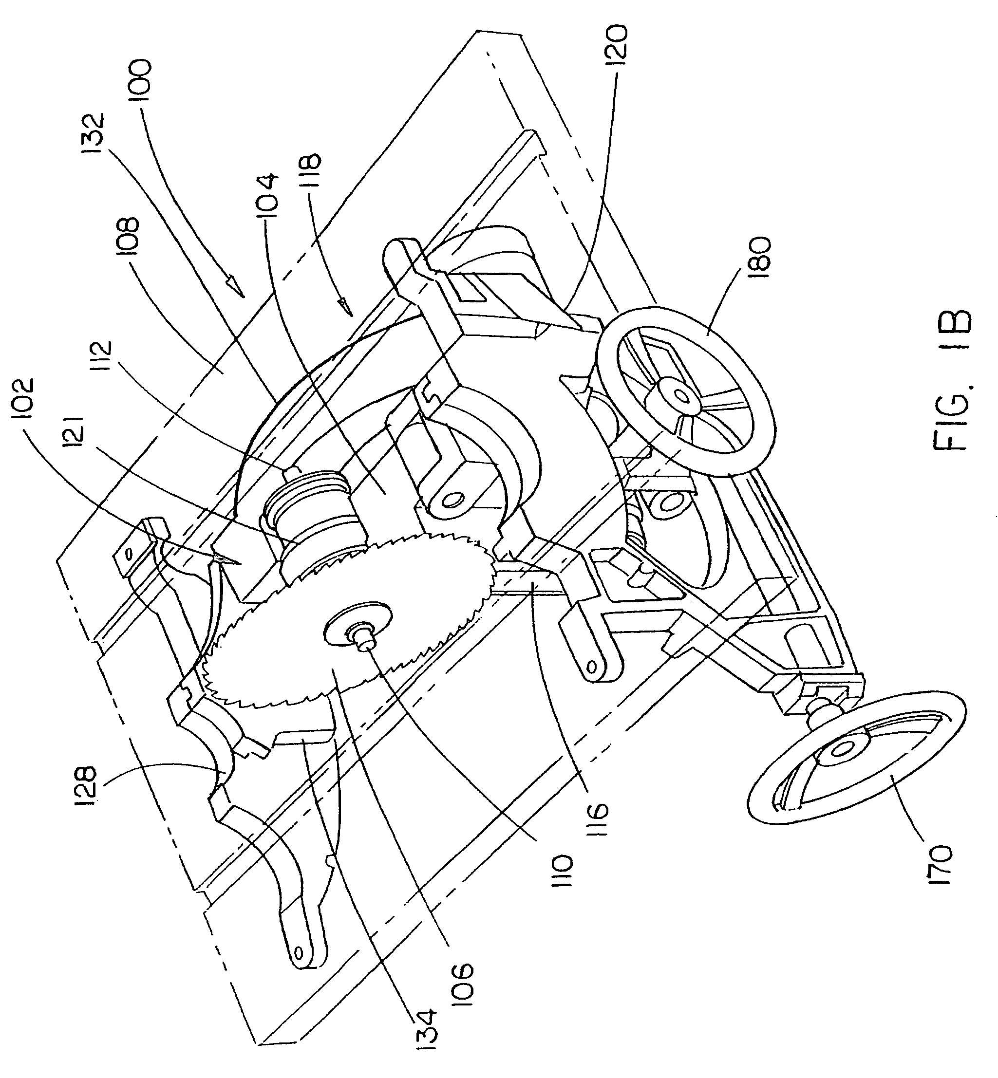
[0055] Referring now to FIGS. 1 through 11, a dual bevel table saw 100 in accordance with exemplary embodiments of the present invention are described. The dual bevel table saw 100 includes a circular saw blade 106 operationally coupled with a motor 114, via an arbor assembly 102. In the present embodiment, the arbor assembly 102 is a dual sided arbor assembly for receiving a saw blade on either a first end or second end. The arbor assembly 102 includes an arbor bracket 104 for supporting an associated blade 106 which may be extended through a table 108. The dual bevel table saw 100 further includes a bevel assembly 118 for adjustably beveling the arbor assembly 102 to establish a plurality of angular settings of the saw blade 106. The circular saw blade 106 may extend through a throat plate assembly 103 which, in the pr...


PUM

PropertyMeasurementUnit
anglesaaaaaaaaaa
anglesaaaaaaaaaa
anglesaaaaaaaaaa

Abstract

An embodiment of the present invention is directed to a riving knife assembly for a dual bevel table saw, comprising: a first armature configured for coupling with a beveling member; a second armature adjustably and rotatably coupled with the first armature; a first mounting member coupled with the second armature; a first riving bracket coupled with the second armature and configured for adjustably coupling with a bearing retaining nut of a dual arbor assembly; a second riving bracket coupled with the first mounting member and configured for adjustably coupling with the inside of a first bore of a first height bracket; a quick release handle disposed upon the first mounting member; an eccentric shaft coupled with the quick release handle; a locking pin having a locking pin body, a second mounting member, a head member coupled with a sheathing member, and a spring loaded assembly, the locking pin operationally coupled with the eccentric shaft; and, a riving knife configured with an engagement assembly for engaging with the locking pin; wherein the spring loaded assembly enables the head member and a circular engagement member disposed on the locking pin body proximal to the head member of the locking pin to be set in a locked position and a release position relative to the second mounting member, the sheathing member and the riving knife; wherein the locked and release positions are established by manipulation of the quick release handle.

Description

CROSS REFERENCE TO RELATED APPLICATIONS [0001] The present application is a continuation-in-part of U.S. application Ser. No. 10 / 968,849 filed on Oct. 19, 2004, which was a continuation-in-part of U.S. application Ser. No. 10 / 698,993 filed on Oct. 31, 2003 which claimed priority under 35 U.S.C. §119(e) to U.S. Provisional Application Ser. No. 60 / 492,095, filed on Jul. 31, 2003 and U.S. Provisional Application Ser. No. 60 / 422,793, filed on Oct. 31, 2002. The U.S. application Ser. Nos. 10 / 968,849, 10 / 698,993, 60 / 492,095, and 60 / 422,793 are herein incorporated by reference in their entireties.FIELD OF THE INVENTION [0002] The present invention generally relates to the field of table saws, and particularly to a riving knife assembly for implementation with a dual bevel table saw having a bevel assembly capable of bi-directional beveling or angling of a saw blade. BACKGROUND [0003] Saw blades beveling is an advantageous capability to be included with power saw assemblies, such as table s...

Claims


Application Information

Patent Timeline
Patent Type & Authority Applications(United States)
IPC IPC(8): B23D45/06B23D45/10B27G19/08
CPCB23D45/067B23D45/10B27G19/08B27B5/30B23D45/105Y10T83/2077Y10T83/8773Y10T83/773Y10T83/7697Y10T83/7726
Inventor GARCIA, JAIME E.WESTON, JEFFREY D.CARROLL, CRAIG A.
Owner BLACK & DECKER INC
Why Eureka
Try Eureka