
Hydrogen storage tank

Inactive Publication Date: 2005-09-01
TOYOTA IND CORP +1
View PDF13 Cites 48 Cited by
  • Summary
  • Abstract
  • Description
  • Claims
  • Application Information

AI Technical Summary

Benefits of technology

[0009] Accordingly, it is an objective of the present invention to provide a hydrogen storage tank that prevents a heat exchanger from being deformed or damaged even if the bulk density of a hydrogen storage alloy is reduced due to expansion and pulverization of the hydrogen storage alloy.

Problems solved by technology

When hydrogen is stored by such compacted hydrogen storage alloy powder, the alloy powder is expanded, which locally generates an excessive stress.
This can adversely affects the tank main body and the heat exchanger in the tank.
However, since the tubes have curved sections, the tubes have the limits in terms of prevention of hydrogen storage alloy sediment.
The method of the publication No. 2001-10801 is therefore hardly reliable.
In such a case, the heat exchanger can be deformed or damaged if excessive pressure in a direction perpendicular to the fins is applied.
None of the publications discloses measures against such a drawback.

Method used


Image

  • Hydrogen storage tank
  • Hydrogen storage tank
  • Hydrogen storage tank

Examples


first embodiment

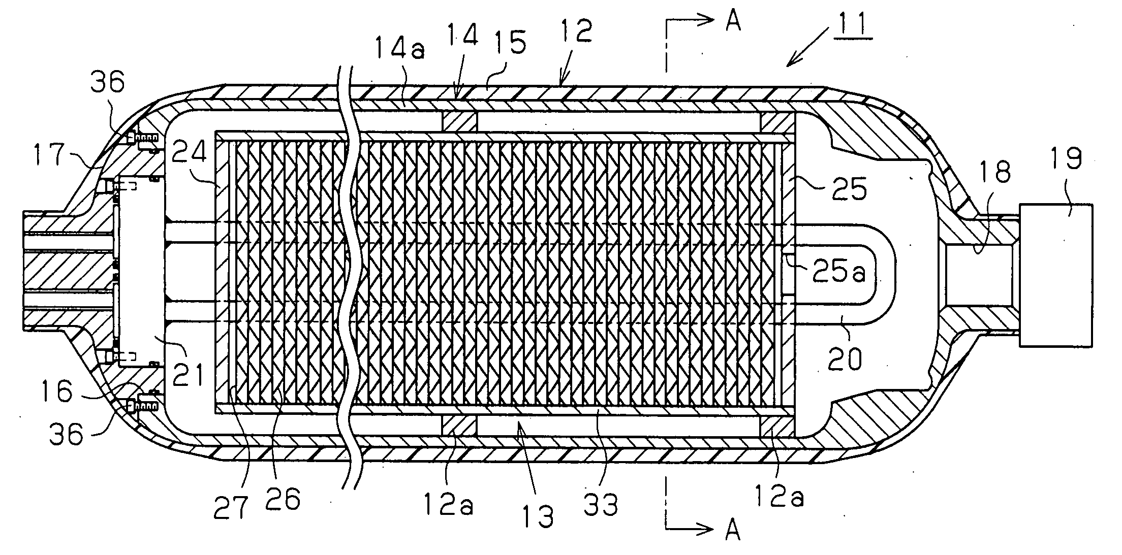
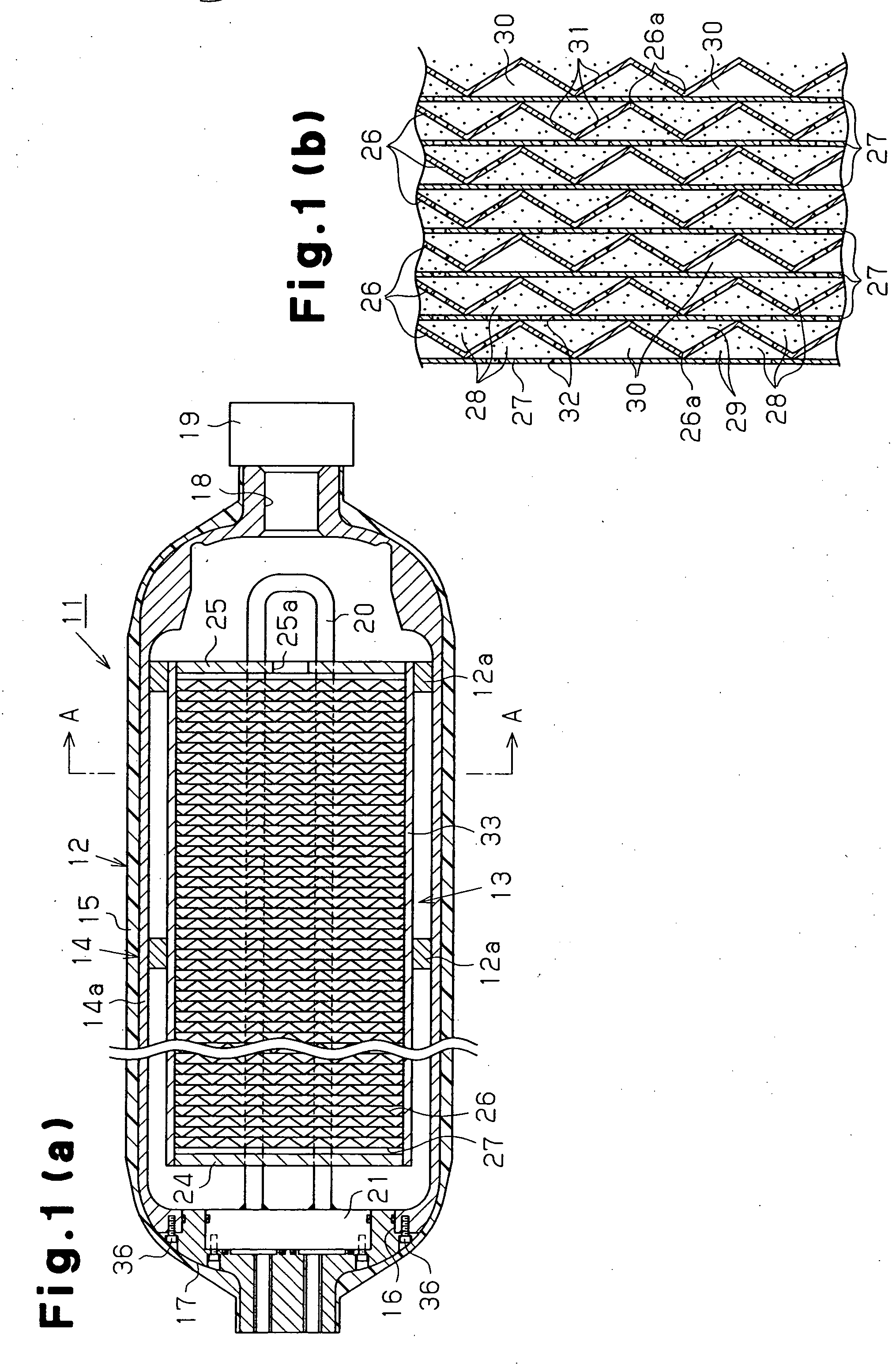
[0021] A hydrogen storage tank 11 according to the present invention will now be described referring to FIGS. 1(a) to 3. FIG. 1(a) shows the orientation of the hydrogen storage tank 11 in use. That is, the vertical direction in the drawing corresponds to the vertical direction of the tank 11 in use.

[0022] As shown in FIG. 1(a), the hydrogen storage tank 11 includes a tubular (in this embodiment, cylindrical) tank main body 12 and a heat exchanger 13. The heat exchanger 13 is accommodated in the tank main body 12. The tank main body 12 includes an elongated hollow liner 14 and a fiber reinforced resin layer 15 that covers the substantially entire outer surface of the liner 14. The liner 14 is made, for example, of an aluminum alloy and makes the tank 11 hermetic. The left end (proximal end) of the liner 14 is formed of separate components. The liner 14 has a substantially tubular liner body 14a, and a lid 17 that closes an opening 16 at the proximal end of the liner body 14a. An open...

second embodiment

[0062] In a configuration where only the absorption portions 37 are provided in a space between each adjacent pair of the heat exchanger fins 27 without providing the sediment limiting portions as in the second embodiment, the number of the absorption portions 37 located in a lower portion of the hydrogen storage tank 11 in use may be greater than the number of the other absorption portions 37. When providing no sediment limiting portions, the MH powder 29 becomes compacted in a lower portion of the hydrogen storage tank 11 in use, which can increase the force due to expansion of the MH powder 29 when hydrogen is stored. However, since the ratio of the absorption portions 37 located in the lower portion is great, the force is smoothly absorbed. The heat exchanger 13 is thus prevented from being deformed or damaged.

[0063] In a configuration where only the absorption portions 37 are provided in a space between each adjacent pair of the heat exchanger fins 27 without providing the sedi...


PUM

PropertyMeasurementUnit
Forceaaaaaaaaaa

Abstract

A tank main body accommodates a heat exchanger including a heating medium pipe. A plurality of heat exchanger fins are coupled to the heating medium pipe to divide the interior of the tank main body into a plurality of spaces. A hydrogen storage alloy is provided in the spaces. An absorption portion is provided in the spaces. The absorption portion is deformed by a force generated by expansion of the hydrogen storage alloy, thereby absorbing the force. Therefore, the heat exchanger is prevented from being deformed or damaged even if the bulk density of the hydrogen storage alloy is reduced due to expansion and pulverization of the hydrogen storage alloy.

Description

BACKGROUND OF THE INVENTION [0001] The present invention relates to a hydrogen storage tank, and more specifically to a hydrogen storage tank that accommodates a hydrogen storage alloy and a heat exchanger. [0002] In recent years, awareness of suppressing global warming has been raised. Particularly, development of fuel cell cars and hydrogen engine cars has been promoted to reduce carbon dioxide emitted from vehicles. In a fuel cell car, hydrogen and oxygen are electrochemically reacted with each other to generate electricity. The generated electricity is supplied to a motor to generate driving force. As a method for supplying hydrogen, there is known a technique in which a hydrogen storage alloy is accommodated in a tank, which alloy stores and releases hydrogen to be utilized. A hydrogen storage alloy generates heat when storing hydrogen and absorbs heat when releasing hydrogen. It is therefore common to provide a heat exchanger in a tank accommodating a hydrogen storage alloy to...

Claims


Application Information

Patent Timeline
IPC IPC(8): B01D53/02B01D59/26F17C11/00F25B17/12F28D7/16F28F1/30H01M8/04H01M8/06
CPCF17C11/005F28D7/06F28D2021/0047F28F1/32Y02E60/50H01M8/04216H01M8/065Y02E60/321H01M8/04208Y02E60/32
Inventor FUJITA, KATSUYOSHIKUBO, HIDEHITOKIMBARA, MASAHIKOMORI, DAIGORO
Owner TOYOTA IND CORP
Learn More