
Variable valve control system for internal combustion engine

a control system and internal combustion engine technology, applied in the direction of valve drives, electric control, machines/engines, etc., can solve the problems of increasing the cost, the deformation of the mountability of the variable valve control mechanism to the engine, etc., to prevent a large relative large variation in the intake air quantity, and large variation in the air fuel ratio

Active Publication Date: 2005-09-01
NISSAN MOTOR CO LTD
View PDF1 Cites 14 Cited by
  • Summary
  • Abstract
  • Description
  • Claims
  • Application Information

AI Technical Summary

Benefits of technology

[0003] With the above-mentioned variable valve control system including the variable lift and working angle control mechanism in JP2001-173469, the valve lift (maximum valve lift) of each of the intake valves is adjusted to be an ultrasmall value such as 1 mm as a minimum valve lift setting, to provide an ultrasmall quantity of intake air which is desired in low-load conditions such as an idle condition. If the intake-valve lift varies from cylinder to cylinder during the intake-valve lift being ultrasmall, the variation causes a relatively large variation in the intake air quantity between the cylinders. This causes a large relative variation in the air fuel ratio between the cylinders. Increasing the minimum valve lift setting to prevent a large relative variation in air fuel ratio between the cylinders reduces advantages of the variable control system, for example, an advantage of the reduction of pumping loss, and an advantage of the enhancement of a response of acceleration from idle conditions.
[0005] Accordingly, it is an object of the present invention to provide a variable valve control system for an internal combustion engine including a plurality of cylinders, which is capable of continuously varying a lift and a working angle of each of intake valves with no undesired phenomenon caused by relative variation in the intake-valve lift characteristic between the cylinders during the engine operating with the minimum intake-valve lift characteristic setting.

Problems solved by technology

This control needs an intricate valve mechanism to provide different valve lift characteristics between the specific part of the cylinders and the other cylinders, resulting in degradation in the mountability of the variable valve control mechanism to the engine and in an increase of the cost.
In addition, initially setting the small valve lift setting in accordance with an initial condition of the cylinder-to-cylinder variation in the intake-valve lift which is dependent on the tolerance of the constituent parts and the tolerance of assembly of the parts is not enough to provide a proper small valve lift characteristic, in consideration of secular change in the variation in the intake-valve lift among the cylinders, which is, for example, produced by the accumulation of carbon and deposit.

Method used


Image

  • Variable valve control system for internal combustion engine
  • Variable valve control system for internal combustion engine
  • Variable valve control system for internal combustion engine

Examples


Embodiment Construction

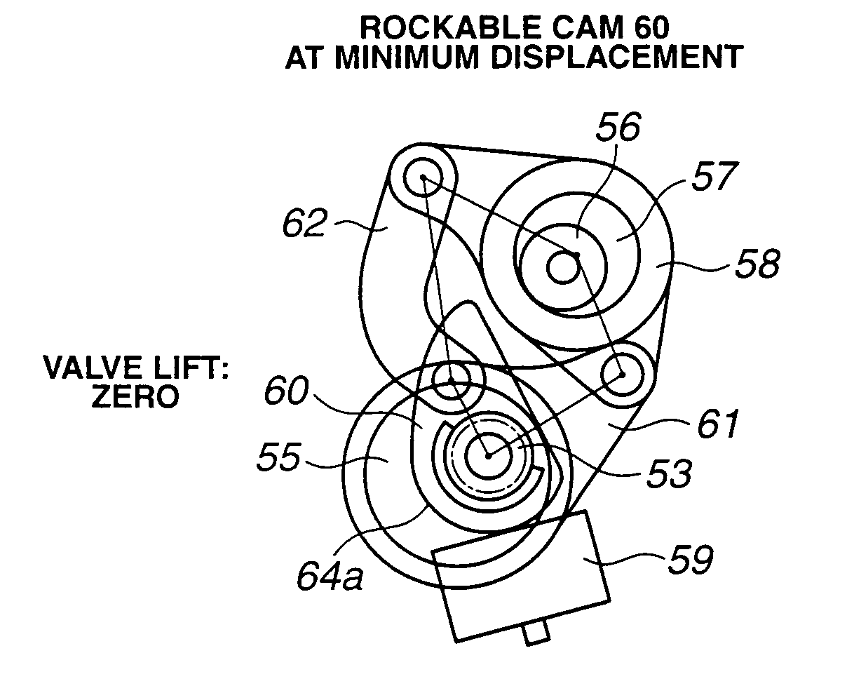
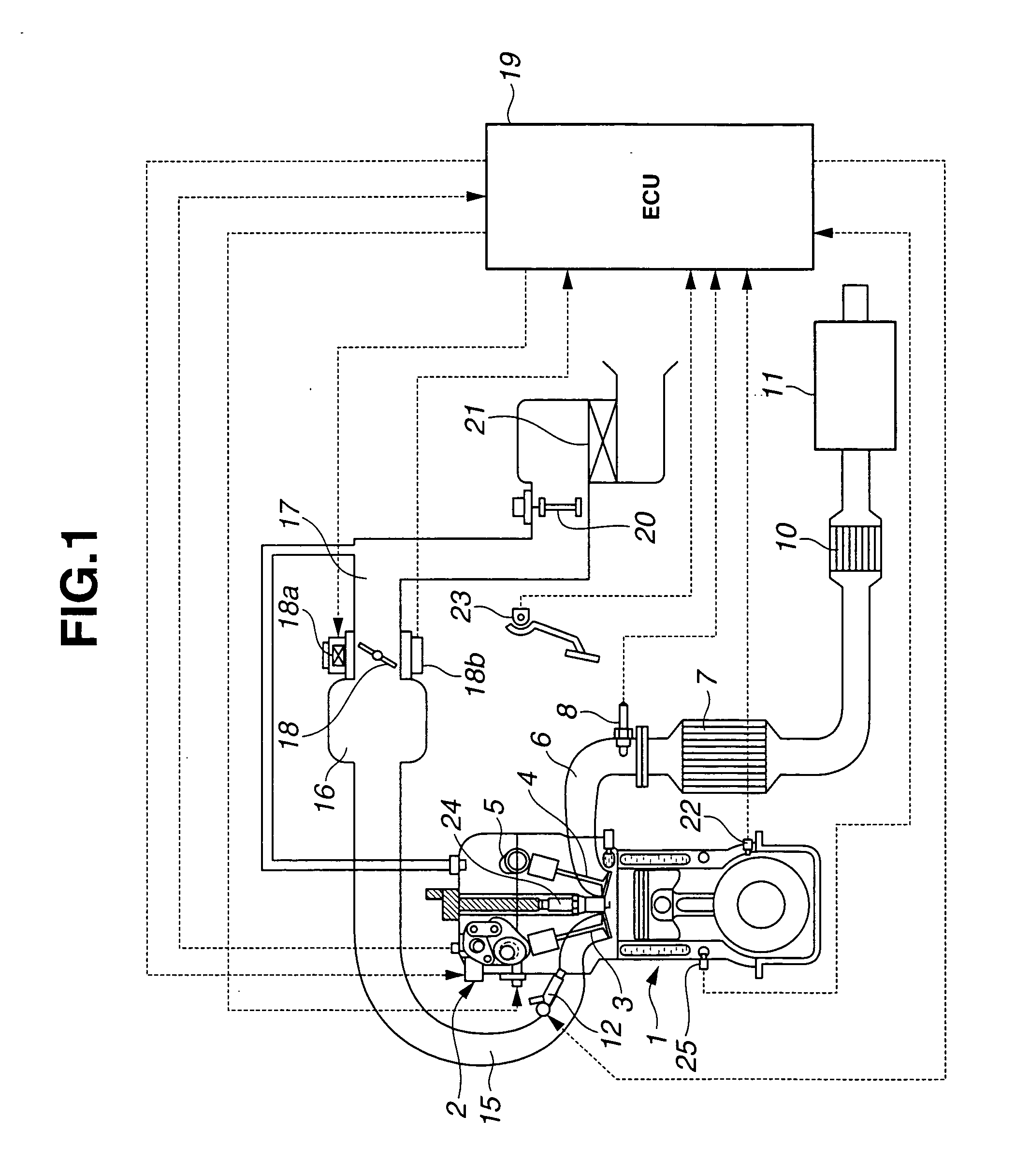
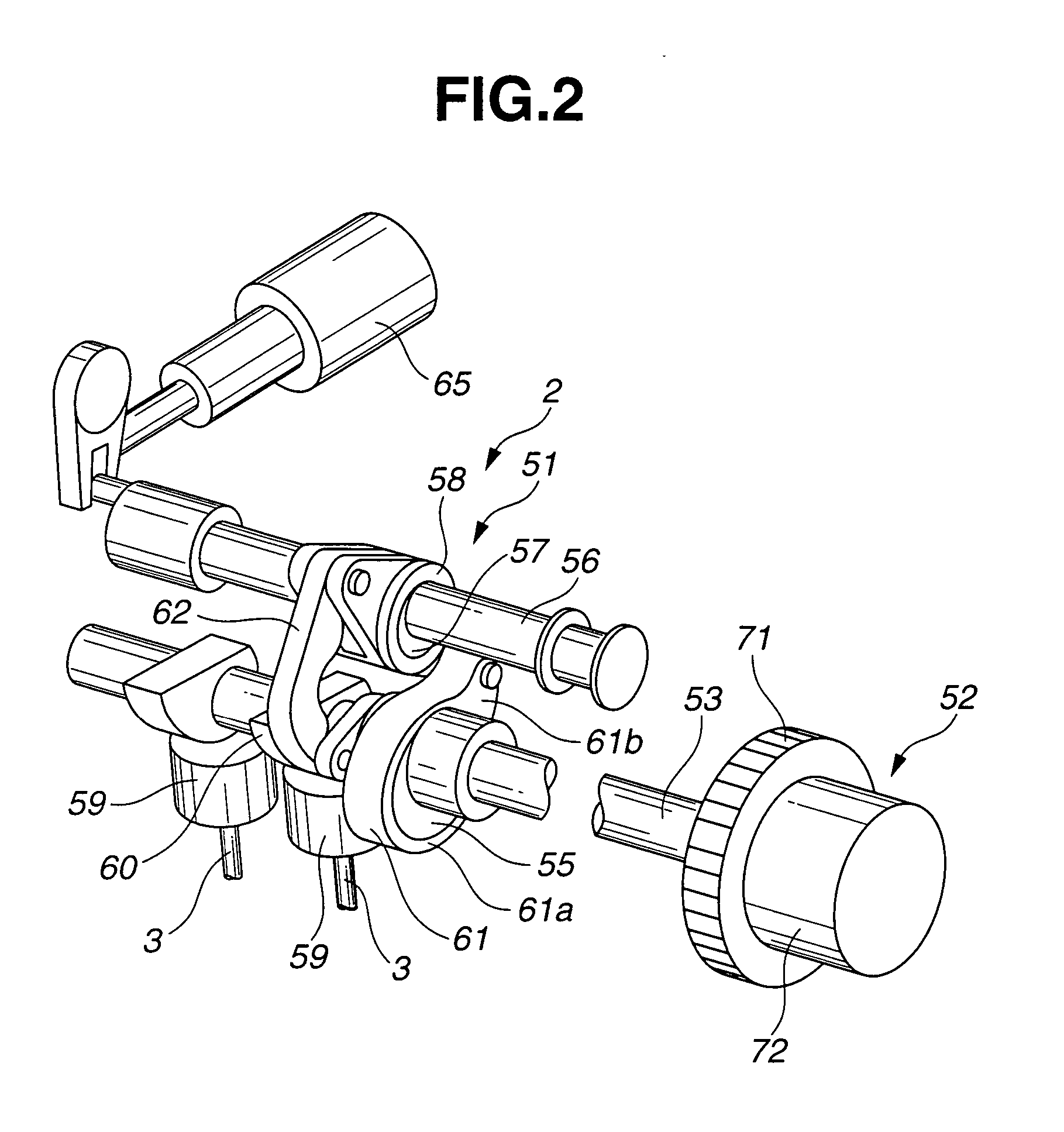
[0032] Referring now to the drawings, particularly to FIG. 1, the variable valve control system of the embodiment is exemplified in an in-line four-cycle spark-ignited gasoline engine 1 with an intake valve 3 and an exhaust valve 4 in each cylinder. However, the present invention is also applicable to an internal combustion engine with other cylinder arrangement such as a V-type engine, and a six-cylinder or other multi-cylinder engine. As shown in FIG. 1, a variable valve actuation mechanism 2 is provided to actuate intake valves 3 so that an intake-valve lift characteristic is variable as fully described later. On the other hand, a valve actuation mechanism for an exhaust valve 4 of each cylinder bank is constructed as a direct-operated valve actuation mechanism that exhaust valve 4 is driven directly by an exhaust camshaft 5. An exhaust-valve lift characteristic is fixed (constant).

[0033] An exhaust manifold 6 is connected to a catalytic converter 7. An air fuel (A / F) ratio sens...


PUM


Abstract

A variable valve control system for an internal combustion engine including a plurality of cylinders, the variable valve control system including a variable lift characteristic control mechanism to adjust a valve lift characteristic of each of intake valves. The variable valve control system is configured to perform determining an engine condition indicator in correlation with an actual relative variation in the valve lift characteristic between the cylinders; determining a desired valve lift characteristic in accordance with an operating condition of the internal combustion engine; controlling the valve lift characteristic of each of the intake valves in accordance with the desired valve lift characteristic; determining the engine condition indicator when the desired valve lift characteristic is equal to a predetermined small valve lift characteristic setting; and expanding the small valve lift characteristic setting if the determined engine condition indicator is larger than a predetermined first threshold value.

Description

BACKGROUND OF THE INVENTION [0001] The present invention relates generally to variable valve control systems for internal combustion engines which are capable of continuously varying a lift and a working angle of an intake valve, and more particularly to a variable valve control system for an internal combustion engine which employs a variable lift and working angle control mechanism to continuously vary a lift and a working angle of an intake valve. [0002] In recent years, there have been proposed and developed various variable valve control systems enabling both a working angle (an operating angle) and a phase to be varied for a high degree of freedom of valve lift characteristics and enhanced engine performance through all engine operating conditions. Such a variable valve control system has been disclosed in Japanese Patent Provisional Publication No. 2001-173469 (hereinafter is referred to as “JP2001-173469”). In the system disclosed in JP2001-173469, a variable lift and workin...

Claims


Application Information

Patent Timeline
IPC IPC(8): F01L1/00F01L1/34F01L13/00F02D13/02F02D41/04F02D41/12F02D41/14F02D43/00F02D45/00
CPCF01L1/022F01L1/024F01L1/344F01L13/0005F01L13/0026F02D2041/002F01L2013/0073F01L2800/00F01L2820/032F02D41/1498F01L2001/0537
Inventor AKASAKA, YUUZOUNOHARA, TSUNEYASUKAWAMURA, KATSUHIKOMIURA, HAJIMENISHII, SATOSHI
Owner NISSAN MOTOR CO LTD
Learn More