

Method of and apparatus for forming rubber strip materials for building tires and method of building tires
a technology of building tires and rubber strips, which is applied in auxillary shaping apparatus, other domestic articles, manufacturing tools, etc., can solve the problems of reducing affecting the weight balance or uniformity of tires, and affecting the quality of rubber strips, etc., so as to reduce the building cycle time per tire, efficiently manufacture, and efficiently manufacture
- Summary
- Abstract
- Description
- Claims
- Application Information
AI Technical Summary
Benefits of technology
Problems solved by technology
Method used
Image

Examples
Embodiment Construction
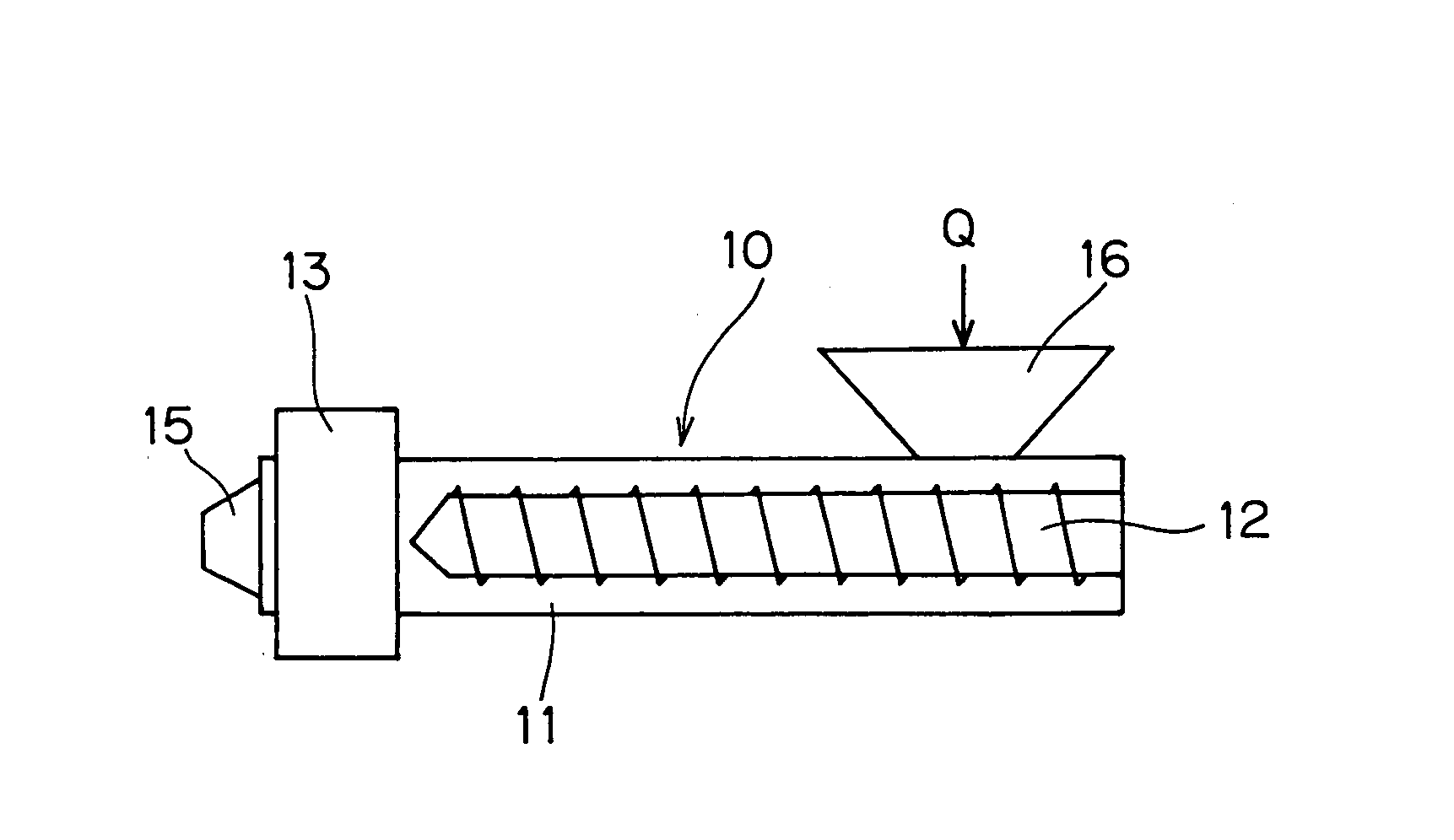
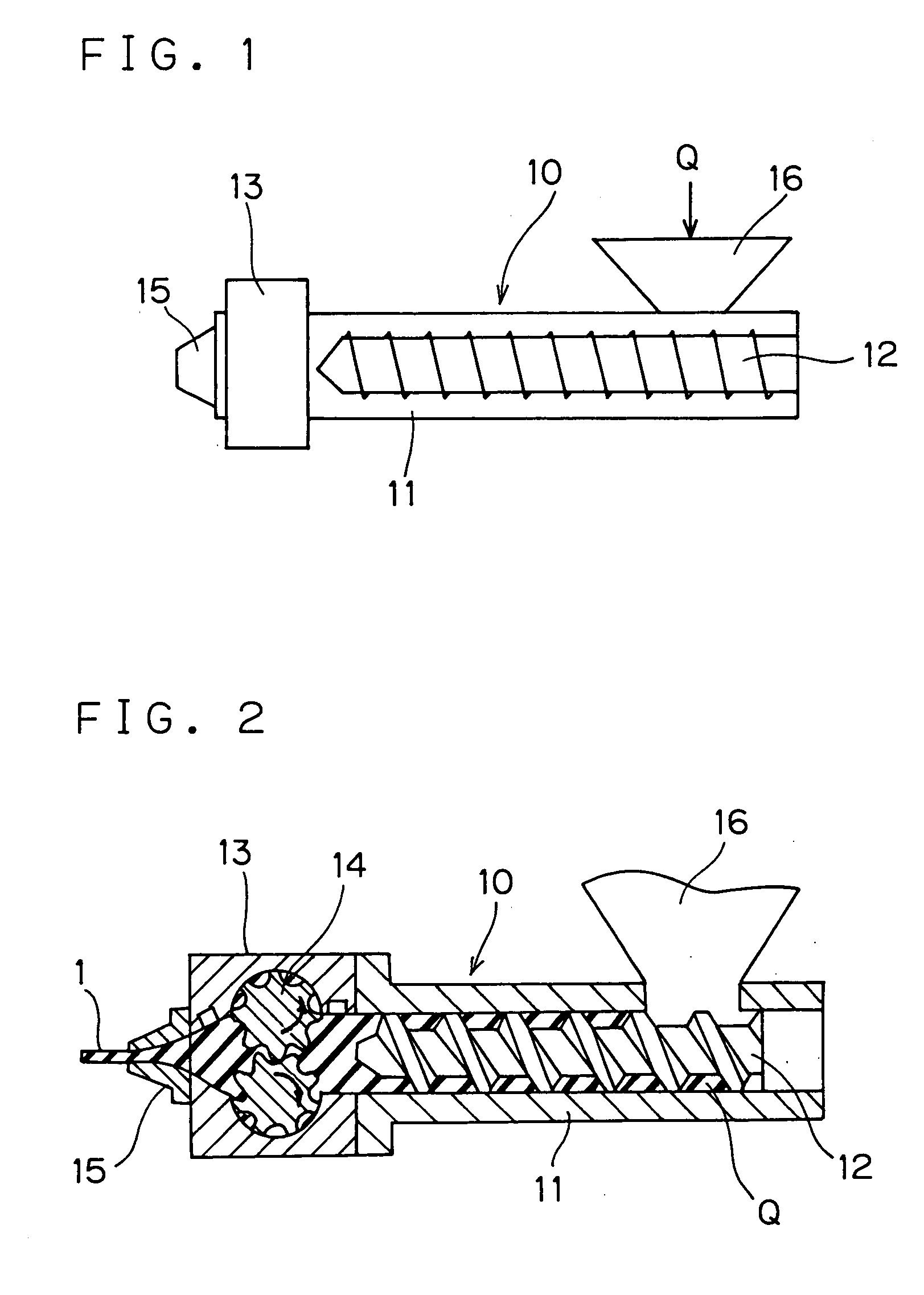
[0033] Modes for carrying out the invention will be described by use of embodiments illustrated by the accompanying drawings.
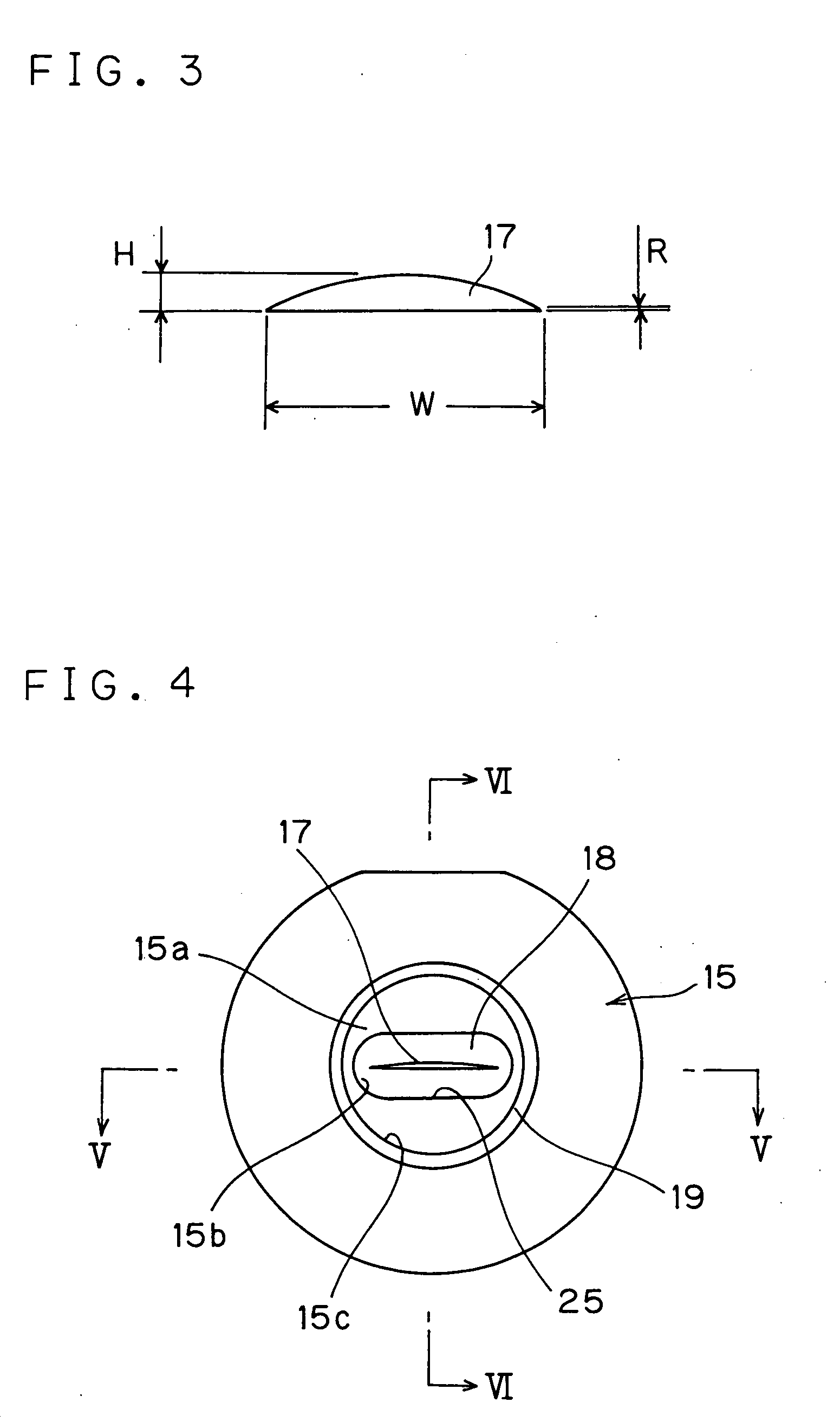
[0034]FIG. 1 is a schematic side view showing an extruder constituting a forming apparatus used in accordance with a rubber-strip forming method of the invention. FIG. 2 is a sectional view explanatory of the above extruder. FIG. 3 is a front view exemplarily showing shape of a discharge port of the die, whereas FIG. 4 is an elevational view of the die seen from rearward and FIGS. 5 and 6 are sectional views of the die.
[0035] According to the invention, a rubber strip 1 as formed is used for manufacturing a tire T as a radial tire shown in FIG. 15, which is comprised of a plurality of rubber parts including: an inner liner rubber part 2, a tread rubber part 3, a side wall rubber part 4, a rim strip rubber part 5 and the like. The rubber strip 1 is used for windingly building at least one of the aforesaid rubber parts, such as the inner liner rubber part 2 or...
PUM
| Property | Measurement | Unit |
|---|---|---|
| thickness | aaaaa | aaaaa |
| thickness | aaaaa | aaaaa |
| thickness | aaaaa | aaaaa |
Abstract
Description
Claims
Application Information