Planar inductive battery charger

Active Publication Date: 2005-09-01
CITY UNIVERSITY OF HONG KONG
View PDF12 Cites 314 Cited by
  • Summary
  • Abstract
  • Description
  • Claims
  • Application Information

AI Technical Summary

Benefits of technology

[0009] It is an advantage of the present invention that in preferred embodiments the planar charging surface may be large enough to receive two or more electronic devices, and the primary charging circuit is adapted to charge two or more devices simultaneously. In this way it is possible to charge more than one device simultaneously. For example the planar charging surface may be divided into a plurality of charging regions, which regions may be defined by providing a plurality of primary transformer windings arranged in a regular array and connecting the windings in groups to define said charging regions. A further advantage of the present invention is that it enables the possibility of allowing a device to move over the charging surface while being charged at the same time. This possibility is particularly useful to a device which is designed to be moved such as a wireless computer mouse
[0010] Viewed from another aspect the present invention provides a battery charging system comprising a charging module comprising a primary charging circuit and being formed with a charging surface for receiving an electronic device to be charged, wherein said charging module comprises a plurality of transformer primary windings arranged in a regular

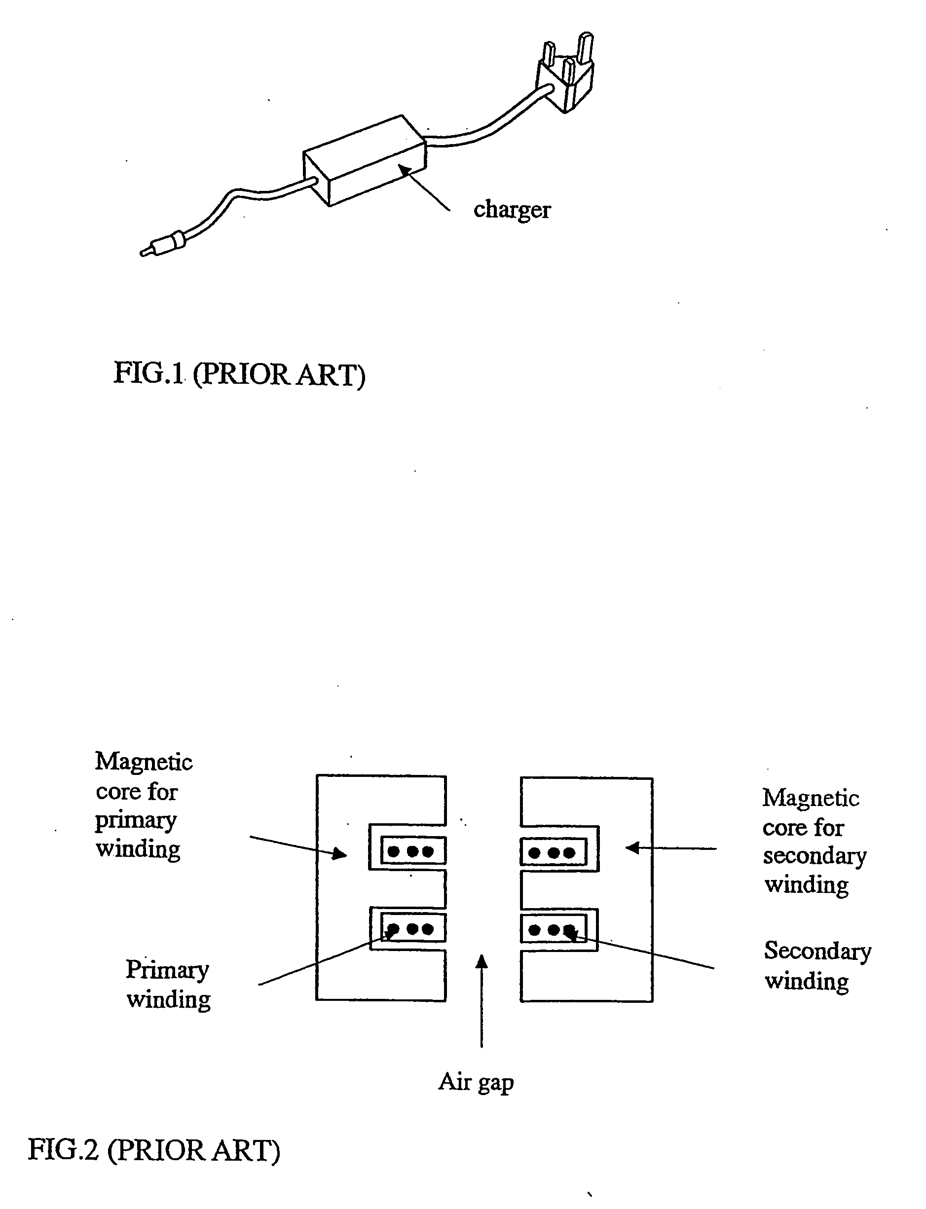
Problems solved by technology

Inductive electronic chargers without direct physical electrical connection have been developed in some portable electronic equipment such as electric toothbrushes where because they are designed to be used in the bathroom in the vicinity of sinks and water, it is not safe to provide a conventional electrical connection.
However, the magnetic flux distribution of a single spiral w

Method used


Image

  • Planar inductive battery charger
  • Planar inductive battery charger
  • Planar inductive battery charger

Examples


Example

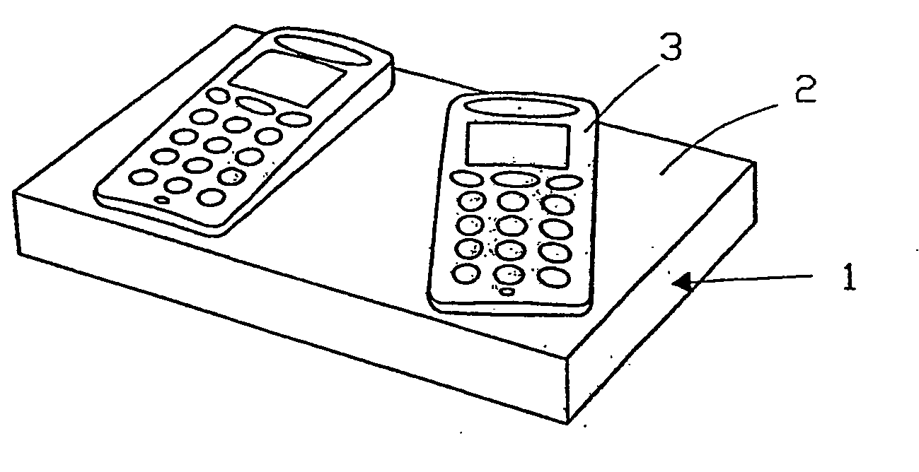
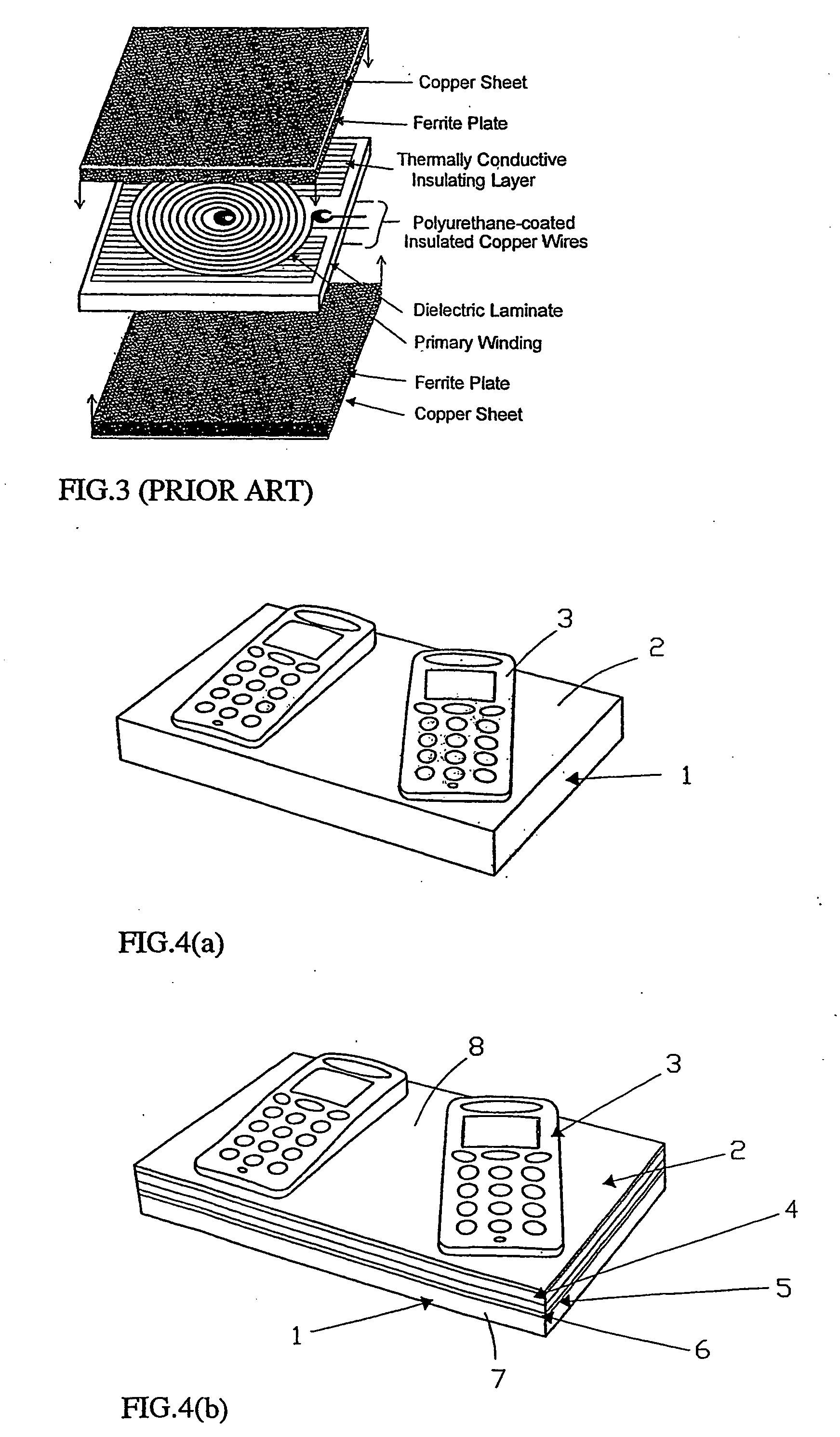
[0069] The present invention will now be described in respect of a preferred embodiment in the form of an inductive battery charger for portable electronic equipment such as mobile phones, handheld computers and personal digital assistants (PDA), and devices such as a wireless computer mouse.

[0070] Referring firstly to FIG. 4, the inductive charger system comprises two modules, a power delivering charger module that contains the primary circuit of a planar isolation transformer and a secondary circuit that is located in the portable electronic equipment to be charged. In this embodiment of the invention, the charger circuit is located within a housing 1 that is formed with a flat charging surface 2. The secondary circuit is formed in the portable equipment to be charged (in this example a mobile phone 3) and the equipment is formed with at least one planar surface. As will be seen from the following description the equipment is charged simply by placing the equipment on the surface...


PUM


Abstract

There is provided a planar inductive battery charging system designed to enable electronic devices to be recharged. The system includes a planar charging module having a charging surface on which a device to be recharged is placed. Within the charging module and parallel to the charging surface is at least one and preferably an array of primary windings that couple energy inductively to a secondary winding formed in the device to be recharged. The invention also provides secondary modules that allow the system to be used with conventional electronic devices not formed with secondary windings.

Description

FIELD OF THE INVENTION [0001] This invention relates to a battery charger, and in particular to a battery charger having a planar surface on which one or more battery powered devices may be placed for battery recharging through induction. The invention also extends to a battery charging system for use with conventional electronic devices and that allows conventional electronic devices to be charged using the battery charging system of the present invention. BACKGROUND OF THE INVENTION [0002] Portable electronic equipment such as mobile phones, handheld computers, personal data assistants, and devices such as a wireless computer mouse, are normally powered by batteries. In many cases, rechargeable batteries are preferred because of environmental and economical concerns. The most common way to charge rechargeable batteries is to use a conventional charger, which normally consists of an AC-DC power supply (in case of using the ac mains) or a DC-DC power supply (in case of using a car b...

Claims


Application Information

Patent Timeline
IPC IPC(8): H01F17/00H01F27/36H01F38/14H02J7/00
CPCH01F17/0006H01F27/365H02J7/025H01F2017/008H01F38/14H02J50/10H02J7/0042H02J50/70H01F27/36H01F27/361
Inventor HUI, SHU-YUEN RON
Owner CITY UNIVERSITY OF HONG KONG
Why Eureka
Try Eureka