
Turbidity sensing system with reduced temperature effects

a turbidity sensor and temperature effect technology, applied in the field of turbidity sensors, can solve the problems of erroneous evaluation results of turbidity signals, turbidity measurement systems almost invariably, and turbidity measurement systems, and achieve the effect of improving thermal behavior

Inactive Publication Date: 2005-09-01
ROSEMOUNT ANALYTICAL
View PDF8 Cites 12 Cited by
  • Summary
  • Abstract
  • Description
  • Claims
  • Application Information

AI Technical Summary

Benefits of technology

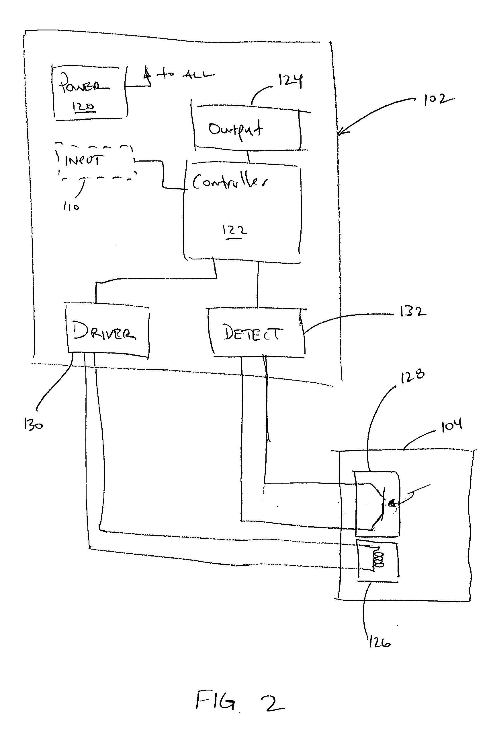
[0009] A turbidity measurement system with an improved thermal behavior is provided. A turbidity measurement system includes an analyzer and one or more turbidity sensors. Each turbidity sensor includes a source of illumination and a semiconductor-based illumination sensor. The dark current of the semiconductor-based illumination sensor is measured when no illumination is provided by the source. This measured dark current is then used to provide a dark current-compensated turbidity measurement.

Problems solved by technology

One of the difficulties with turbidity measurement systems arises from the nature of such systems.
Specifically, turbidity measurement systems almost invariably employ optical techniques to arrive at a turbidity measurement.
In such applications, if temperature compensation were not provided, temperature fluctuations would be interpreted as fluctuations in the turbidity value and would lead to erroneous results in the evaluation of the turbidity signal.
While attempts have been made to address the temperature effects on turbidity measurement systems, such attempts have generally employed additional temperature measurement devices, and / or complex algorithms to generate a temperature-compensated output.
The more elaborate the apparatus and accompanying techniques used to provide temperature-compensation, the more costly the turbidity measurement system becomes.
Furthermore, such approaches will generally fail if the temperature sensor itself begins to deteriorate, or otherwise become inaccurate.

Method used


Image

  • Turbidity sensing system with reduced temperature effects
  • Turbidity sensing system with reduced temperature effects
  • Turbidity sensing system with reduced temperature effects

Examples


Embodiment Construction

[0014] While embodiments of the present invention will be described with respect to removing “dark current” related to temperature from turbidity measurements, embodiments of the present invention are practicable with any photosensitive element having a variable dark current, which variability is undesired in photosensing.

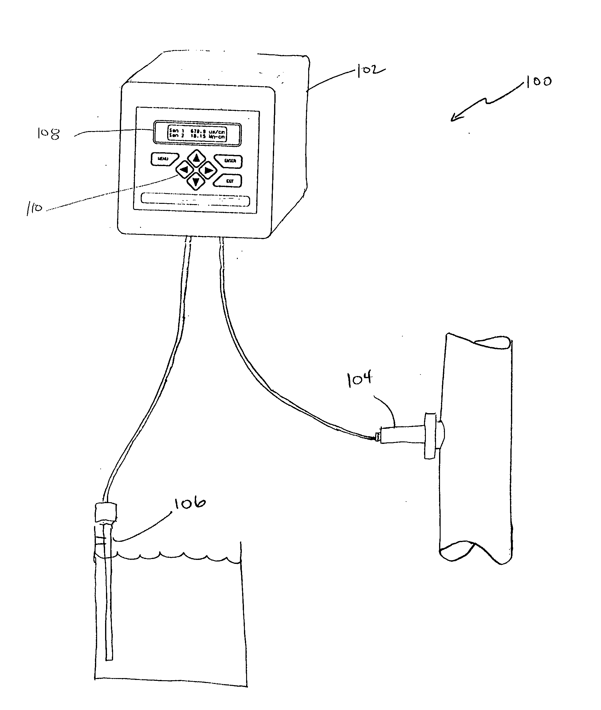
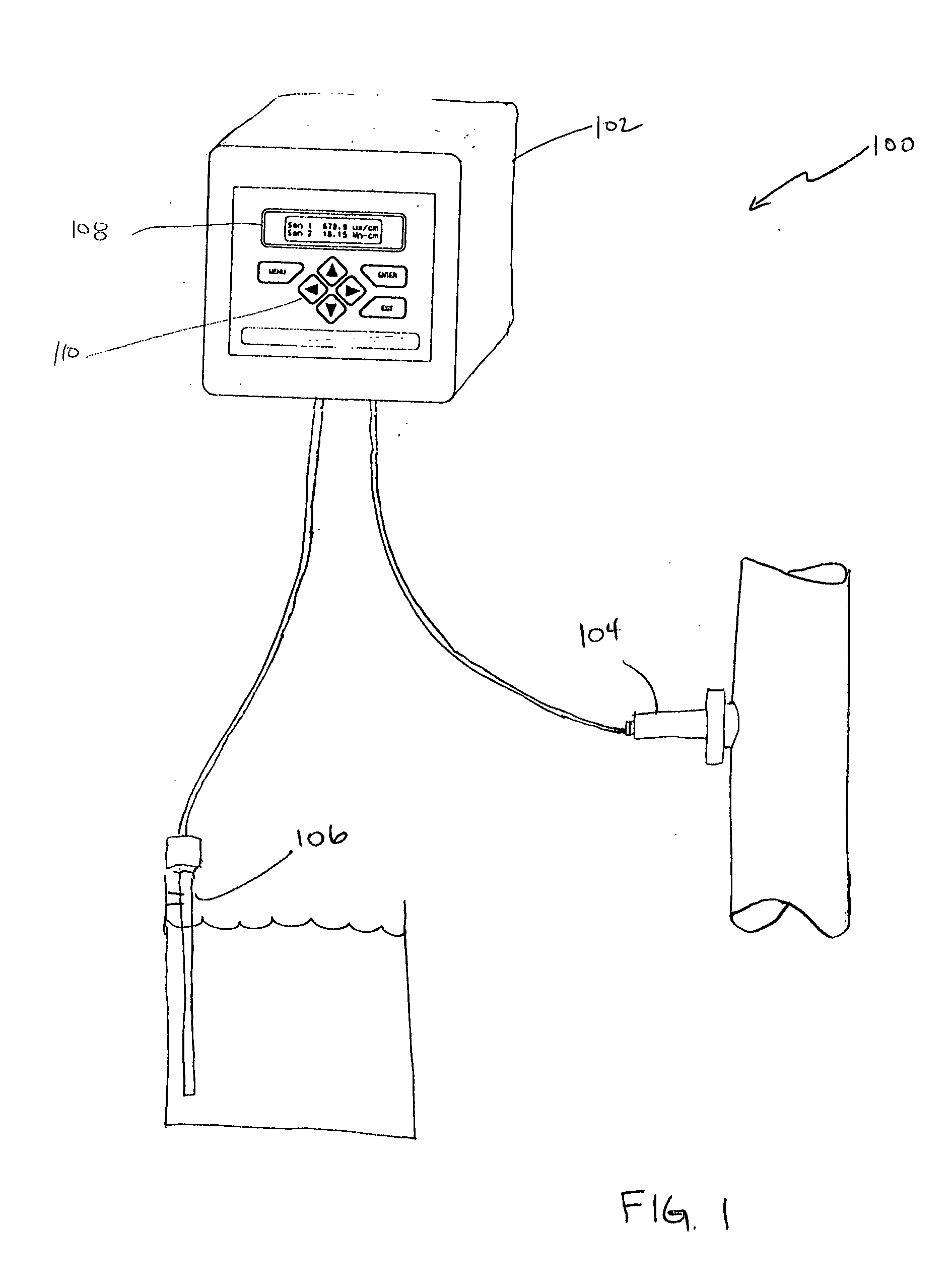
[0015]FIG. 1 is a diagrammatic view of turbidity sensing system 100 with which embodiments of the present invention are particularly useful. System 100 includes a turbidity analyzer or meter 102 coupled to one or more turbidity sensors 104, 106. Turbidity sensors may be any suitable types of turbidity sensors including an insertion-type turbidity sensor 104, and / or a submersion-type sensor 106. Further, any type of electromagnetic radiation may be used as illumination for the turbidity sensors. For example, sensors in compliance with U.S. EPA regulation 180.1 that use visible light can be used. Additionally, sensors in accordance with ISO 7027, which use near infr...


PUM

PropertyMeasurementUnit
turbidityaaaaaaaaaa
dark currentaaaaaaaaaa
digital turbidityaaaaaaaaaa

Abstract

A turbidity measurement system with an improved thermal behavior is provided. A turbidity measurement system includes an analyzer and one or more turbidity sensors. Each turbidity sensor includes a source of illumination and a semiconductor-based illumination sensor. The dark current of the semiconductor-based illumination sensor is measured when no illumination is provided by the source. This measured dark current is then used to provide a dark current-compensated turbidity measurement.

Description

CROSS-REFERENCE TO CO-PENDING APPLICATION [0001] The present application is based on and claims the benefit of U.S. provisional patent application Ser. No. 60 / 548,084, filed Feb. 26, 2004, the content of which is hereby incorporated by reference in its entirety.BACKGROUND OF THE INVENTION [0002] The present invention relates to turbidity sensors. More particularly, the present invention relates to turbidity sensors and the effect of temperature on such sensors. [0003] Turbidity sensors essentially measure the “cloudiness” of a fluid such as water. This measurement is generally done by directing one or more beams of light, either visible or invisible, into the fluid and detecting the degree to which light is scattered off of solid particles suspended in the fluid solution. The resulting turbidity measurement is generally given in Nephelometric Turbidity Units (NTU). [0004] Turbidity measurement systems are used in a wide array of applications including water and waste water monitorin...

Claims


Application Information

Patent Timeline
Patent Type & Authority Applications(United States)
IPC IPC(8): A47L15/42D06F39/00G01N21/00G01N21/27G01N21/49G01N21/53
CPCG01N21/274G01N21/53G01N2201/12707G01N2201/127G01N2201/0218
Inventor CIOBANU, CALINREZVANI, BEHZAD
Owner ROSEMOUNT ANALYTICAL
Learn More