Method and apparatus for temperature stabilization of a wavelength of a laser

a technology of temperature stabilization and laser, applied in the field of high-speed optical communication, can solve problems such as limiting the performance of dwdm systems

Active Publication Date: 2005-09-01
LUCENT TECH INC
View PDF4 Cites 15 Cited by
  • Summary
  • Abstract
  • Description
  • Claims
  • Application Information

AI Technical Summary

Benefits of technology

[0008] Another aspect of the invention is an apparatus facilitating

Problems solved by technology

However, in operation, there may be a need to modify a bias current of the laser chip to compensate for changes in the optical output power when, for example, the laser degrades over time.
In this case, the wavele

Method used


Image

  • Method and apparatus for temperature stabilization of a wavelength of a laser
  • Method and apparatus for temperature stabilization of a wavelength of a laser
  • Method and apparatus for temperature stabilization of a wavelength of a laser

Examples


Embodiment Construction

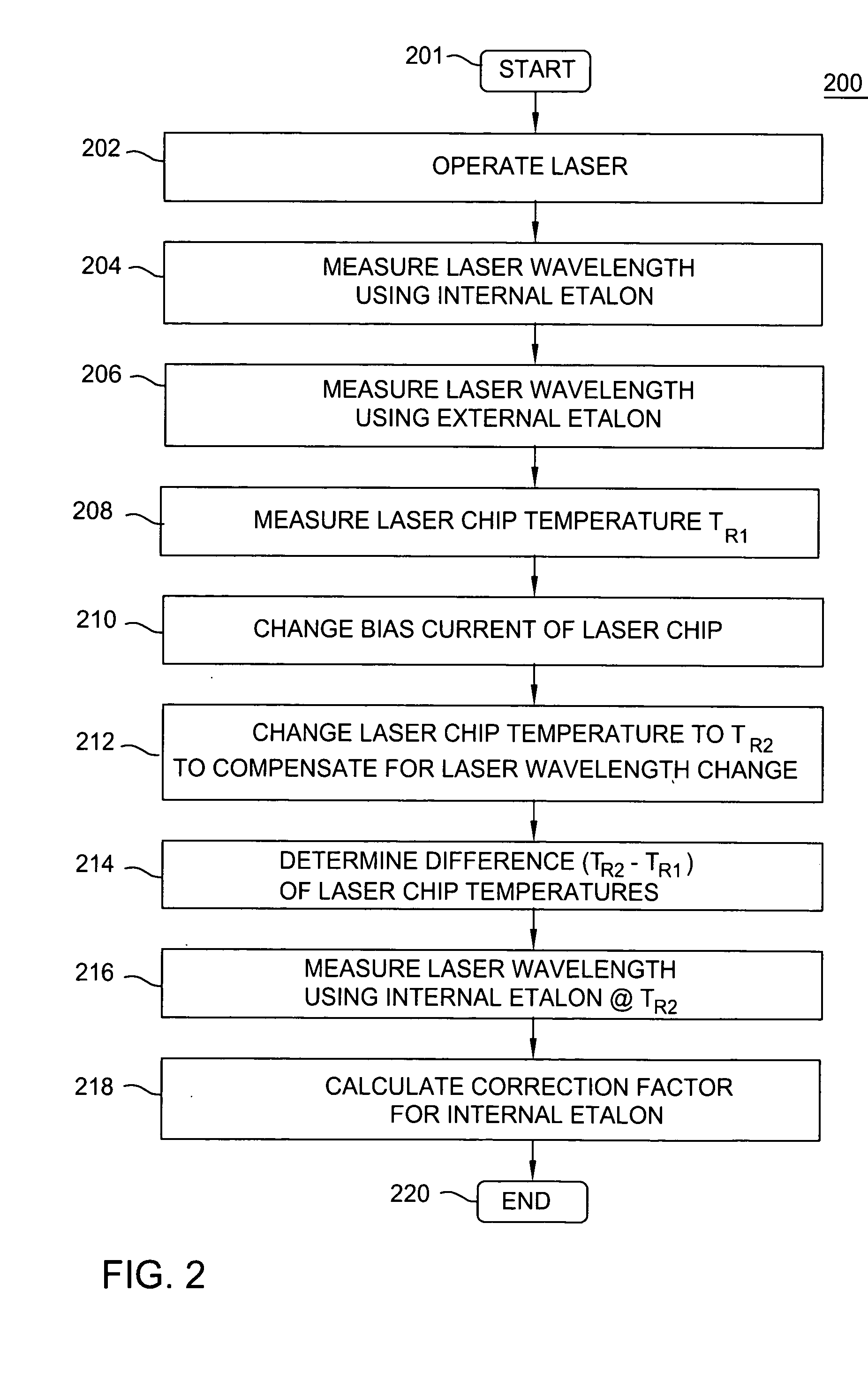
[0015] The present invention advantageously provides stabilization of a wavelength of a laser (e.g., semiconductor diode laser in a dense wavelength division multiplexing (DWDM) system) by compensating for thermal instability of a laser chip and an internal wavelength locker (i.e., etalon) utilizing the results of measuring the wavelength of the laser using an external wavelength meter.

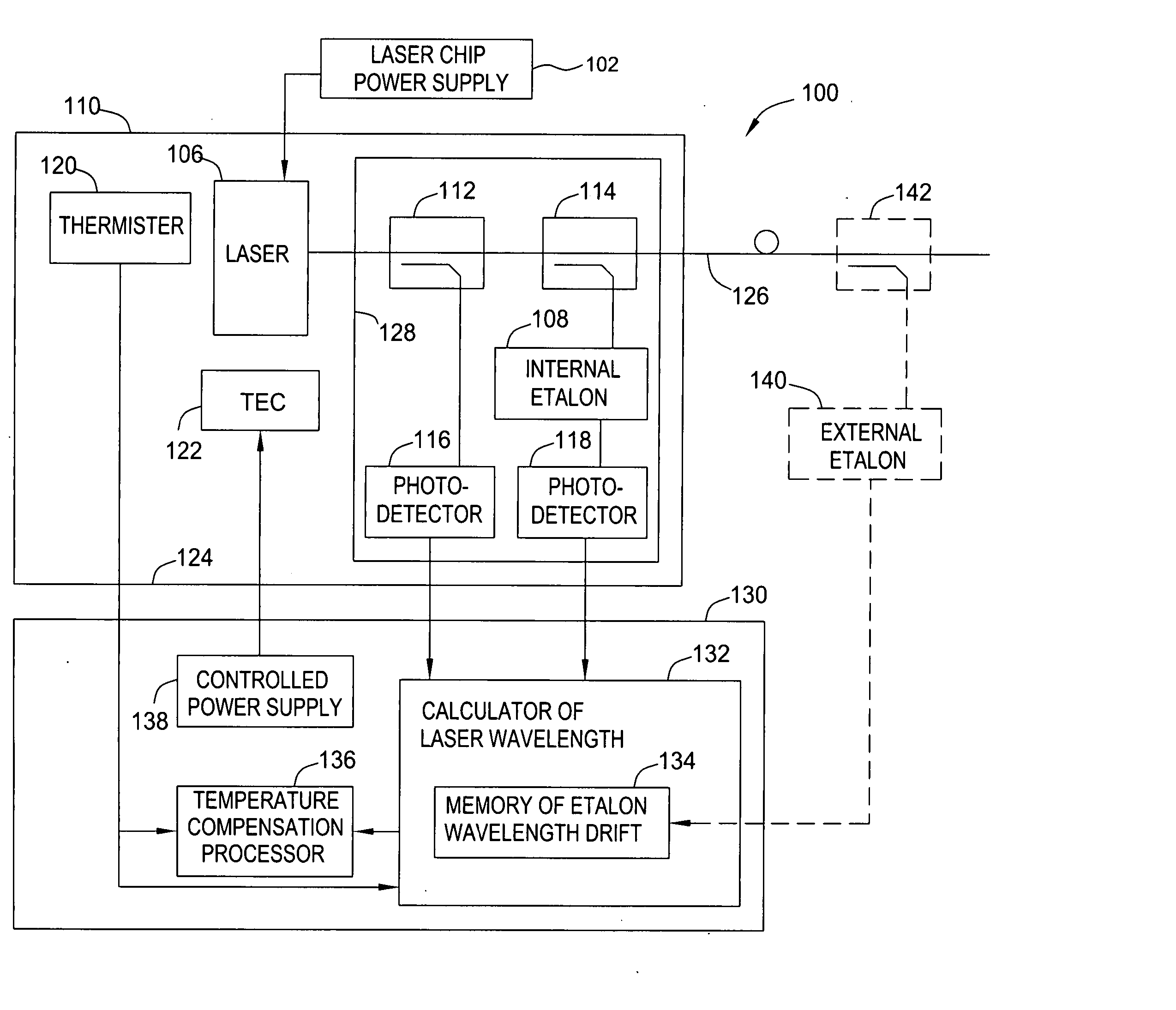
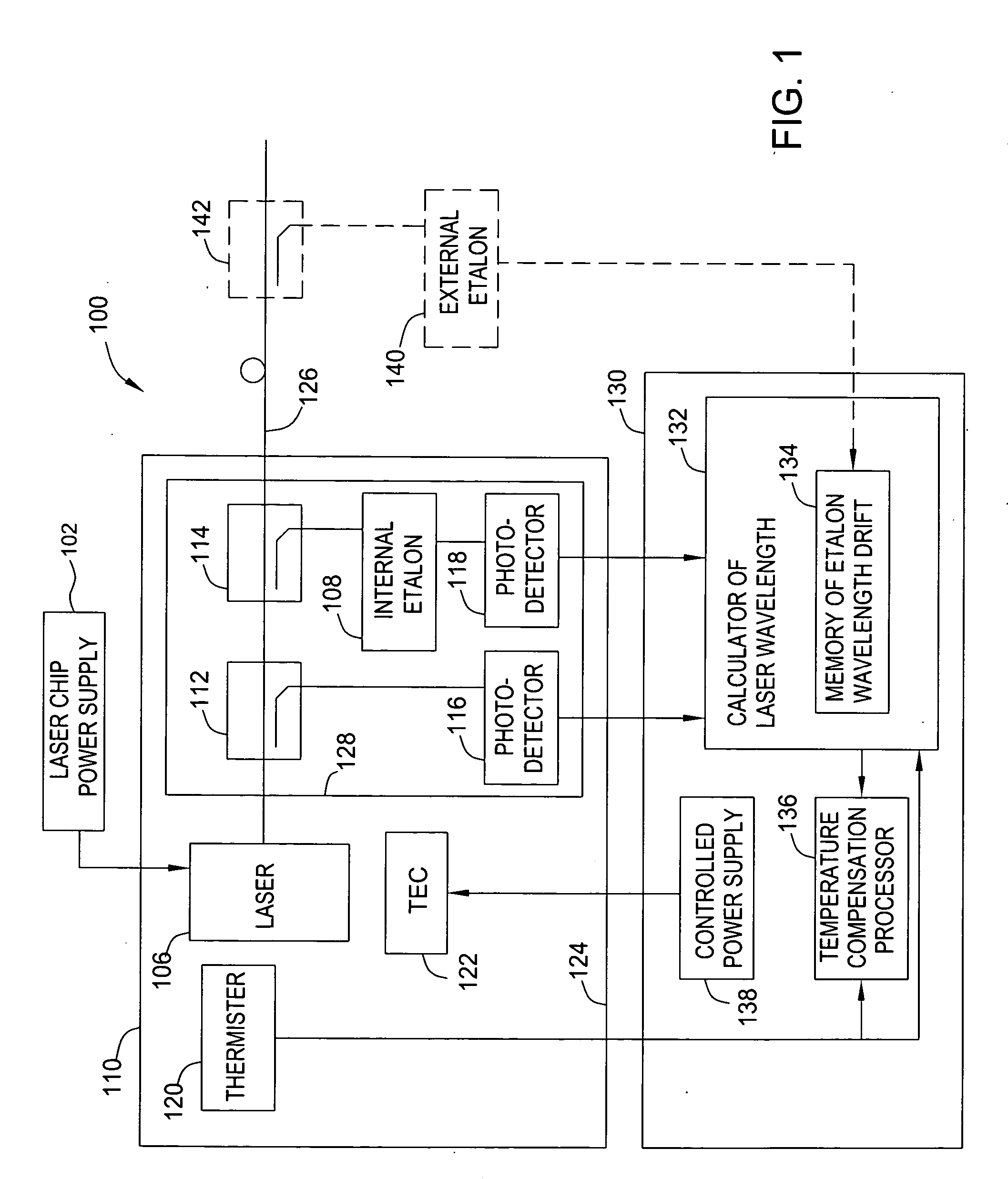
[0016]FIG. 1 depicts an exemplary block diagram of a laser 100 which wavelength may be temperature stabilized in accordance with one embodiment of the present invention. The laser 100 comprises an integrated laser chip assembly 110, a laser chip power supply 102, and a temperature controller 130. The laser chip assembly 110 generally includes a laser chip 106, a wavelength locker 128, a thermoelectric module (TEC) 122, and a temperature sensor 120, which are disposed in a sealed enclosure 124. In one embodiment, the wavelength locker 128 comprises broadband optical couplers 112 and 114, an internal w...


PUM


Abstract

A method and apparatus for temperature stabilization of a wavelength of a laser compensate for thermal instability of a internal etalon of the wavelength using the results of measuring the wavelength with an external wavelength meter.

Description

FIELD OF THE INVENTION [0001] The present invention generally relates to the field of high-speed optical communications and, more specifically, to dense wavelength division multiplexing (DWDM) systems. BACKGROUND OF THE INVENTION [0002] In high-speed optical communications, a method of wavelength division multiplexing (DWDM) is used to increase transmission capacity of an optical fiber. A DWMD system comprises a plurality of transmission lasers, which operate at different wavelengths and are coupled to the same single-mode fiber. A wavelength of a laser should be stabilized within a narrow range corresponding to an optical transmission channel of the system. [0003] The wavelength of the laser strongly depends on a temperature of a laser chip. The laser generally includes an internal wavelength locker measuring the wavelength of the laser and a temperature control circuit to compensate for temperature instability of the laser chip. Both the laser chip and the internal wavelength lock...

Claims


Application Information

Patent Timeline
IPC IPC(8): H01S5/024H01S5/068H01S5/0687
CPCH01S5/02415H01S5/0687H01S5/06804
Inventor GRONBACH, SIEGFRIED
Owner LUCENT TECH INC
Why Eureka
Try Eureka