Videoendoscopic system

a technology of endoscopic and video, applied in the field of video endoscopic system, can solve the problems of large manufacturing cost and handling difficulties, and achieve the effect of preventing light fogging

Active Publication Date: 2005-09-01
OLYMPUS WINTER & IBE
View PDF7 Cites 27 Cited by
  • Summary
  • Abstract
  • Description
  • Claims
  • Application Information

AI Technical Summary

Benefits of technology

[0009] The image window and light window can be arranged outside the axis of the cylinder. However, the image window preferably is advantageously arranged centrally with respect to the axis of the cylinder. Since the image window is situated in the axis of the shaft in the conventional construction, the cylinder is also situated concentrically with respect to the axis of the shaft. An overall central construction is thus produced with many structural advantages.
[0010] The windows can be disposed in the end surfaces of the cylinder and the bore respectively. If

Problems solved by technology

Of disadvantage with the known devices is the construction of the coupling with two parallel cylinders, which are arranged next to one another and fit into correspondi

Method used


Image

  • Videoendoscopic system
  • Videoendoscopic system

Examples


Embodiment Construction

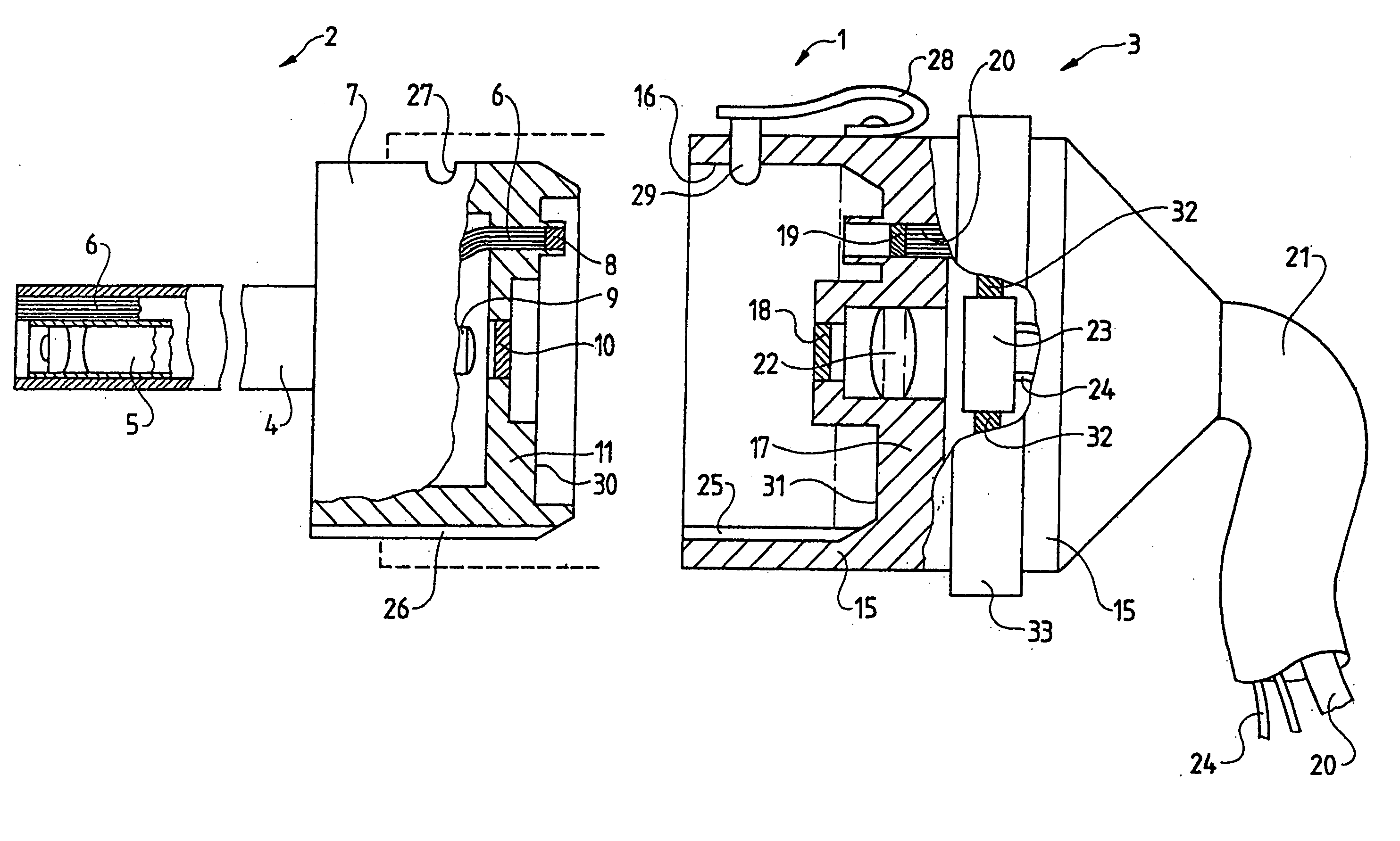
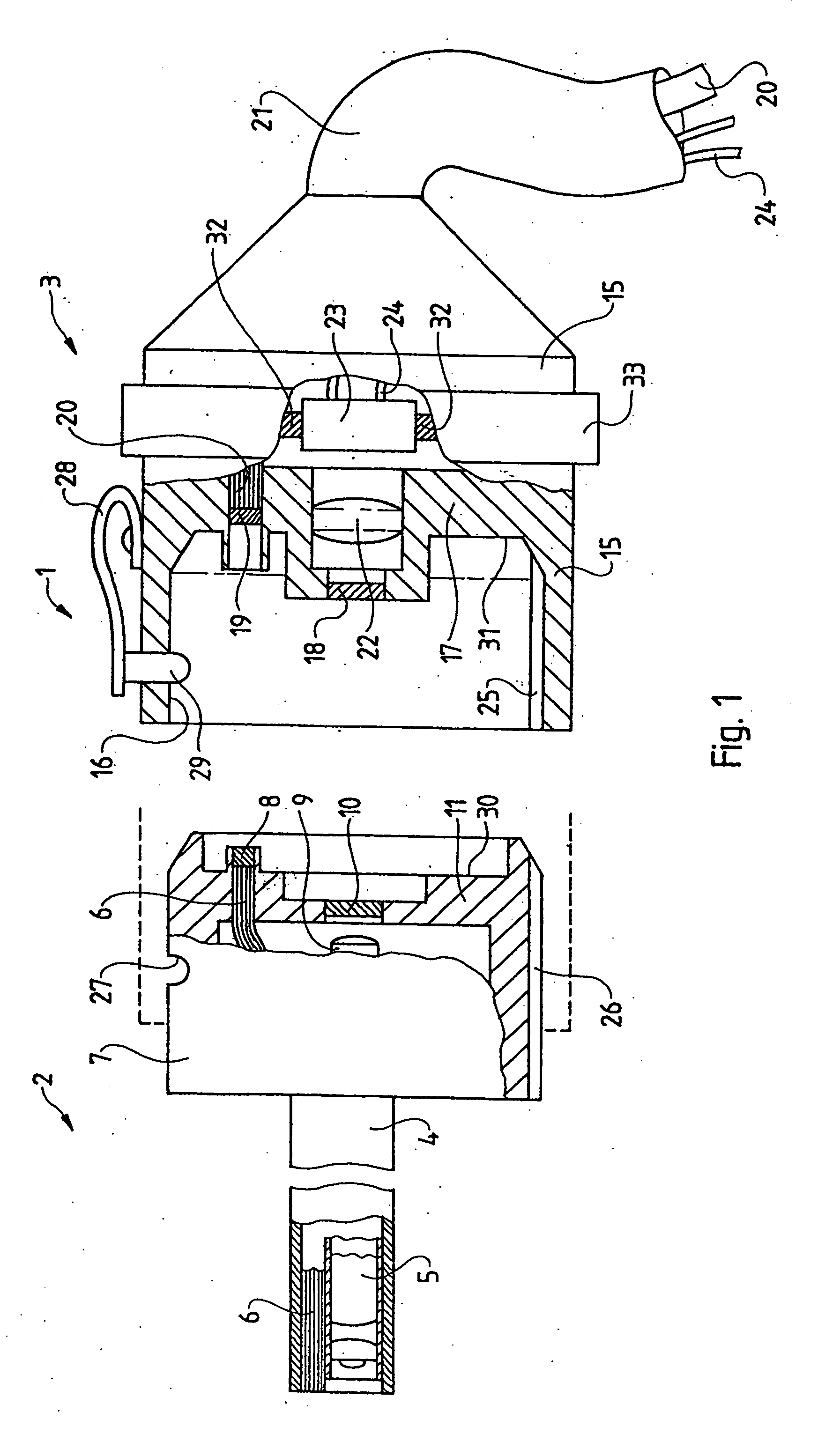
[0013]FIG. 1 shows a videoendoscopic system 1 consisting of an endoscope optical system 2 and a camera portion 3, which are constructed so that they may be coupled to one another. The endoscope optical system 2 has an elongate shaft 4, through which an optical image guide 5 passes, which is constructed in the exemplary embodiment in form of a relay lens system. Also passing through the shaft parallel to the optical image guide 5 is a fibre light guide 6, which radiates at the distal end of the shaft 4 parallel to the viewing direction.

[0014] At the proximal end of the shaft 4, the endoscope optical system 2 has an end housing 7, in which, as the partially sectioned view shows, the fibre light guide 6 terminates in front of a light entry window 8.

[0015] The optical image guide 5 terminates with a proximal end lens 9 in front of an image exit window 10.

[0016] The end housing 7 is constructed with a cylindrical peripheral shape with a cylinder axis, which passes centrally through th...


PUM


Abstract

A videoendoscopic system (1) including an endoscope optical system (2) and a camera portion (3), the endoscope optical system (2) having an elongated shaft (4) through which an optical image guide (5) and a fiber light guide (6) pass, and an end housing (7), which is proximally connected to the shaft (4) and has an image exit window (10) and a light entry window (8) with radiation directions that are parallel to one another and to the axis of the shaft (4). The camera portion (3) includes a camera housing (15), from which an image signal cable (24) and a light guide cable (20) pass out, and an image entry window (18) and a light exit window (19), which are arranged with parallel radiation directions at a distance from the windows (8, 10) in the end housing (7) and the end housing (7). The camera housing (15) is constructed with a rotationally fixedly lockable coupling device (7, 16, 25, 26, 19) for coupling the windows (8, 19; 10, 18) to one another in a centering manner. The the coupling device has a cylinder (7) on one of the housings and a matching bore (16) on the other housing (15). The windows (8, 10; 19, 18) are arranged in the end wall (11) of the cylinder (7) and the base wall (17) of the bore (16).

Description

BACKGROUND OF THE INVENTION [0001] 1. Field of the Invention [0002] The invention relates to a videoendoscopic system. [0003] b 2. Description of Related Art [0004] Such systems are disclosed in U.S. Pat. No. 5,682,199 and U.S. Pat. No. 6,494,826 B1. These prior systems both consist of an endoscope optical system and a camera housing which may be connected by means of a coupling, whereby both the image is coupled in one direction and the light is coupled in the other direction through the coupling point with appropriate windows. This manner of construction provides a series of advantages. [0005] Of disadvantage with the known devices is the construction of the coupling with two parallel cylinders, which are arranged next to one another and fit into corresponding parallel bores in the opposing housing. The result of this is a complex housing structure with correspondingly large manufacturing costs and difficulties in handling. SUMMARY OF THE INVENTION [0006] The object of the present...

Claims


Application Information

Patent Timeline
IPC IPC(8): A61B1/00A61B1/04G02B23/24G02B23/26G03B29/00H04N5/225H04N7/18
CPCA61B1/042A61B1/00128A61B1/00126G02B23/2484
Inventor DEHMEL, JOACHIMFORSTER, THOMASKRAAS, MATHIASSPAHN, GILBERT
Owner OLYMPUS WINTER & IBE
Why Eureka
Try Eureka