Control system for belt-type continuously variable transmission

a control system and transmission technology, applied in mechanical equipment, instruments, gearing, etc., can solve the problems of increasing the consumption of power to establish high oil pressure, deteriorating durability, and degrading the transmission efficiency of power, so as to eliminate the influence of disturban

Inactive Publication Date: 2005-09-01
TOYOTA JIDOSHA KK
View PDF23 Cites 19 Cited by
  • Summary
  • Abstract
  • Description
  • Claims
  • Application Information

AI Technical Summary

Benefits of technology

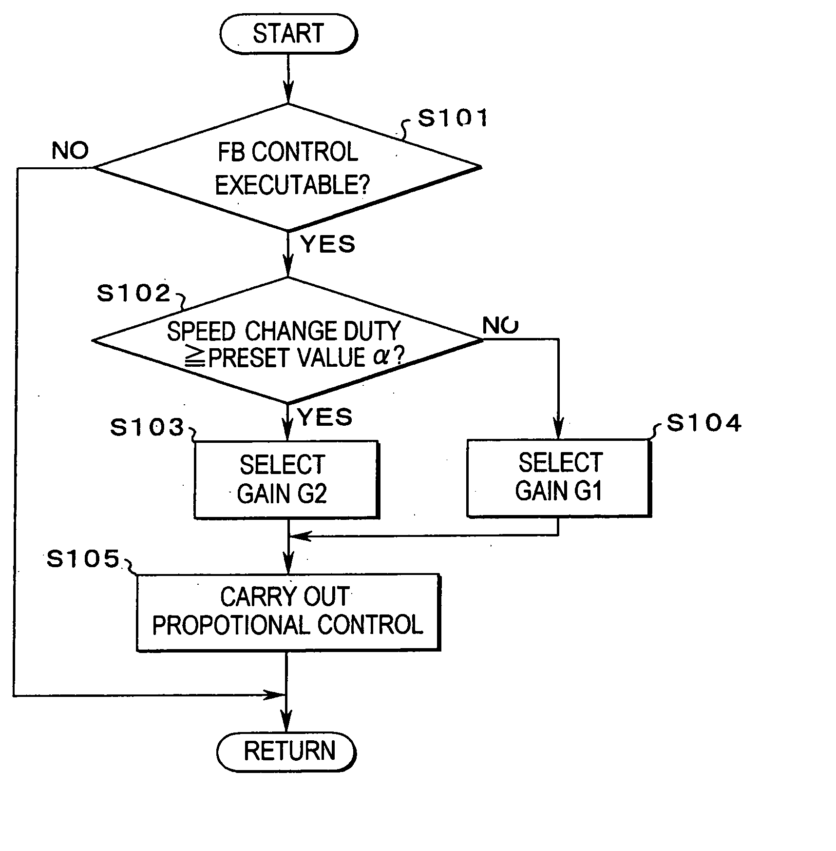
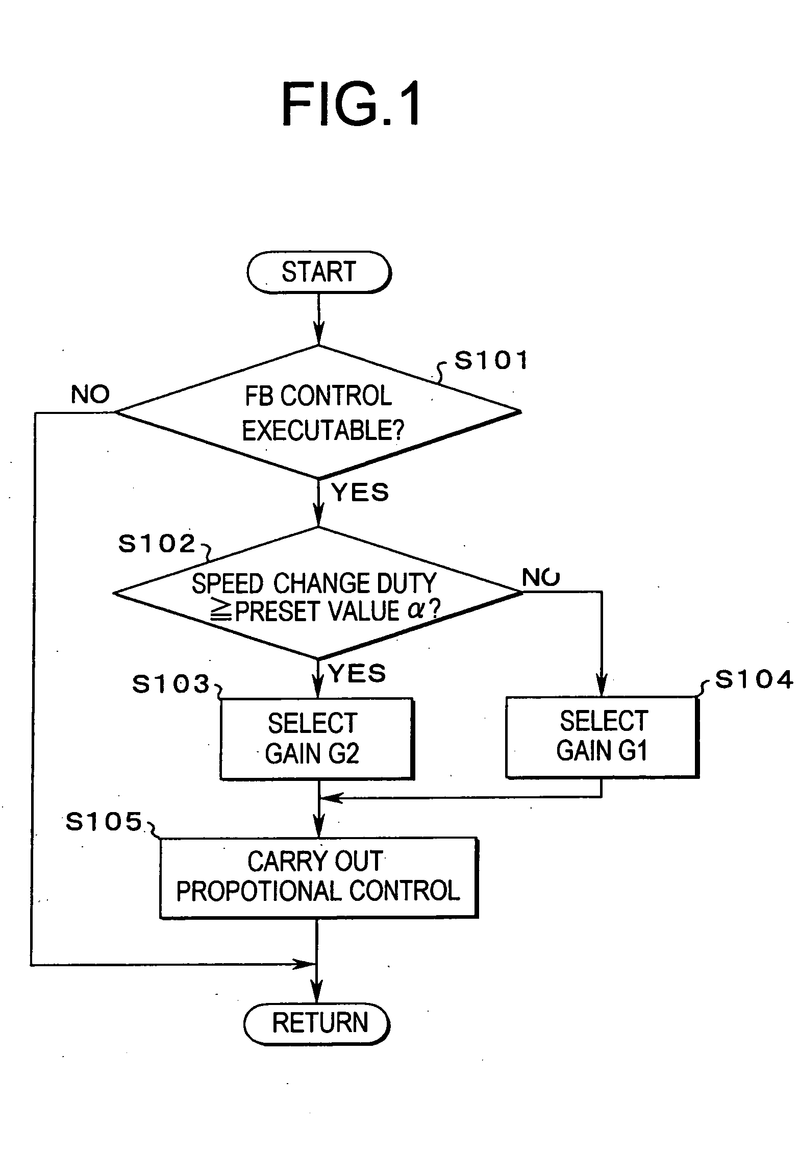
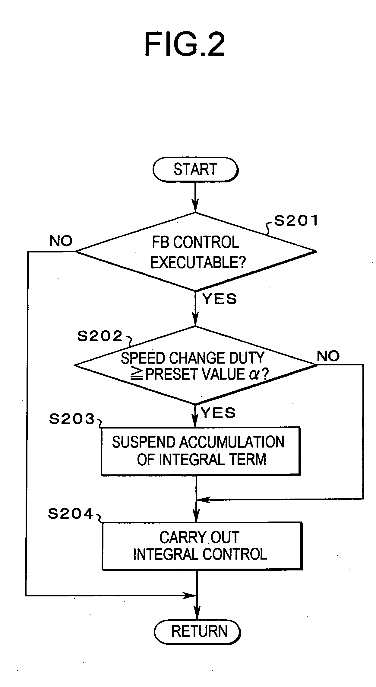
[0014] An object of this invention is to provide a control system, which is capable of properly controlling an oil pressure applied to a pulley even when a pressure-receiving capacity is changed as a result of a speed change or the like. More specifically, the object of this invention is to control a pressure for establishing a clamping pressure accurately when carrying out a feedback control on the clamping pressure for clamping a belt, by eliminating influences of disturbance caused by the change in the pressure-receiving capacity of an actuator as far as possible.

Problems solved by technology

However, if the clamping pressure is excessively high, transmission efficiency of the power is degraded in the continuously variable transmission, and consumption of the power is increased to establish high oil pressure.
However, any of the inventions suggested by the above-mentioned publications does not consider the pressure change resulting from the change in the pressure-receiving capacity of the oil chamber at the speed change time.
This may increase power loss and deteriorate durability.

Method used


Image

  • Control system for belt-type continuously variable transmission
  • Control system for belt-type continuously variable transmission
  • Control system for belt-type continuously variable transmission

Examples


Embodiment Construction

[0039] This invention will be described in connection with its specific examples. First of all, here will be described one example of a drive line including a prime mover and a continuously variable transmission, to which the invention is applied. FIG. 8 schematically shows one example of the drive line including a belt type continuously variable transmission 1. This continuously variable transmission 1 is connected to a prime mover 5 through a forward / backward switching mechanism 2 and through a fluid transmission mechanism 4 having a lockup clutch 3.

[0040] The prime mover 5 is constructed of an internal combustion engine, or an internal combustion engine and an electric motor, or an electric motor and so on. In the following description, the prime mover 5 will be called as “engine 5”. On the other hand, the fluid transmission mechanism 4 has a similar construction to a torque converter of the background art. Specifically, the fluid transmission mechanism 4 is configured to includ...


PUM


Abstract

A control system for controlling a belt-type continuously variable transmission having a pulley capable of varying its groove width to which a belt is applied, in which the pulley is provided with an oil chamber to which the oil pressure is fed so that the pulley clamps the belt, in which the capacity of the oil chamber is varied in accordance with a change in the groove width, and in which the oil pressure in the oil chamber is controlled in accordance with a deviation between a target oil pressure and an actual oil pressure, comprising: a pressure-receiving capacity change detecting device for detecting a change in the capacity of the oil chamber; and an oil pressure control contents altering device for altering a degree to reflect the deviation on the oil pressure control of the oil chamber on the basis of a change in the capacity.

Description

BACKGROUND OF THE INVENTION [0001] 1. Field of the Invention [0002] This invention relates generally to a belt-type continuously variable transmission, in which a speed change ratio is varied continuously by changing effective running radii of a belt applied on a drive pulley and a driven pulley having variable groove widths. More particularly, this invention relates to a control system of the continuously variable transmission. [0003] The disclosure of Japanese Patent Applications No. 2004-34037 filed on Feb. 10, 2004, and No. 2004-363420 filed on Dec. 15, 2004, including specification, drawings and claims is incorporated herein by reference in its entirety. [0004] 2. Discussion of the Related Art [0005] In the prior art, it is known to optimize the running state of an engine by arranging a continuously variable transmission on the output side of the engine, and by continuously controlling a gear ratio of the continuously variable transmission. As the continuously variable transmis...

Claims


Application Information

Patent Timeline
Patent Type & Authority Applications(United States)
IPC IPC(8): F16H9/12F16H9/00F16H59/00F16H59/06F16H61/00F16H61/02F16H61/06F16H61/662
CPCF16H61/66272F16H2061/0078Y10T477/6242F16H2059/683F16H2059/702
Inventor OSHIUMI, YASUHIROIWATSUKI, KUNIHIROAMAYA, TAKAYUKI
Owner TOYOTA JIDOSHA KK
Why Eureka
Try Eureka