Blood pressure measuring device

a measuring device and blood pressure technology, applied in the field of blood pressure measuring devices, can solve the problems of subject pain, affecting the accuracy of measurement, restricting the posture of a subject at the time, etc., and achieve the effect of hardly causing pain to a subject and high accuracy

Active Publication Date: 2005-09-01
OMRON HEALTHCARE CO LTD
View PDF10 Cites 29 Cited by
  • Summary
  • Abstract
  • Description
  • Claims
  • Application Information

AI Technical Summary

Benefits of technology

[0013] An object of the present invention is to provide a blood pressure measuring device provided with an automatic cuff winding mechanism that enables measurement of a blood pressure value with high accuracy, hardly causes pain to a subject during the measurement, and allows the subject to keep an unconstrained posture during the measurement.
[0024] In the blood pressure measuring device according to the present invention, the pivot connection mechanism preferably includes at least one of a dumper and a friction spring for suppressing abrupt pivotal movement of the second enclosure.
[0027] According to the present invention, the subject can take an unforced posture during the measurement, without suffering pain, so that accurate and stable measurement of the blood pressure value becomes possible.

Problems solved by technology

The blood pressure monitors disclosed therein, however, pose the following problems.
Firstly, in each of the blood pressure monitors provided with automatic cuff winding mechanisms disclosed in Japanese Patent Laying-Open Nos. 10-314123 and 10-314125, a living body insert portion including a hollow opening into which an arm is inserted is integral with a main unit incorporating a cuff winding mechanism, thereby restricting the posture allowed to a subject at the time of measurement.
Thus, if the inclination angle of the living body insert portion and the inclination angle of the subject's arm inserted do not match, there occurs a gap between the cuff and the arm, in which case the arm cannot be pressed uniformly, leading to degradation of accuracy in measurement.
Further, the subject would feel pain, since he / she needs to keep a constrained posture during the measurement.
Although the degree of freedom of the posture upon measurement is somewhat improved compared to the automatic cuff winding mechanism disclosed in Japanese Patent Laying-Open Nos. 10-314123 and 10-314125, the problem has not been solved completely.
Further, since the winding mechanism is elastically biased with the plate spring or the coil springs, large flexure of the springs will apply load on the cuff by their elastic force, causing degradation of measurement accuracy.
The blood pressure monitor shown in FIG. 27, however, poses an additional problem as follows.
Such adjustment while upper arm 320 is being inserted in the hollow opening is very tiresome, thereby imposing an unnecessary burden on subject 300.

Method used


Image

  • Blood pressure measuring device
  • Blood pressure measuring device
  • Blood pressure measuring device

Examples


first embodiment

[0057] A blood pressure monitor according to the present embodiment detects arterial pressure pulse waves by pressing an upper arm of a subject, to measure a blood pressure value. The blood pressure monitor of the present embodiment is provided with an automatic cuff winding mechanism to wind a cuff around the upper arm.

[0058] Firstly, a basic configuration of the blood pressure monitor of the present embodiment will be explained with reference to FIGS. 1-3.

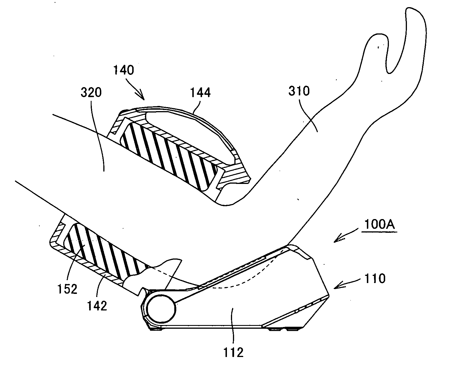
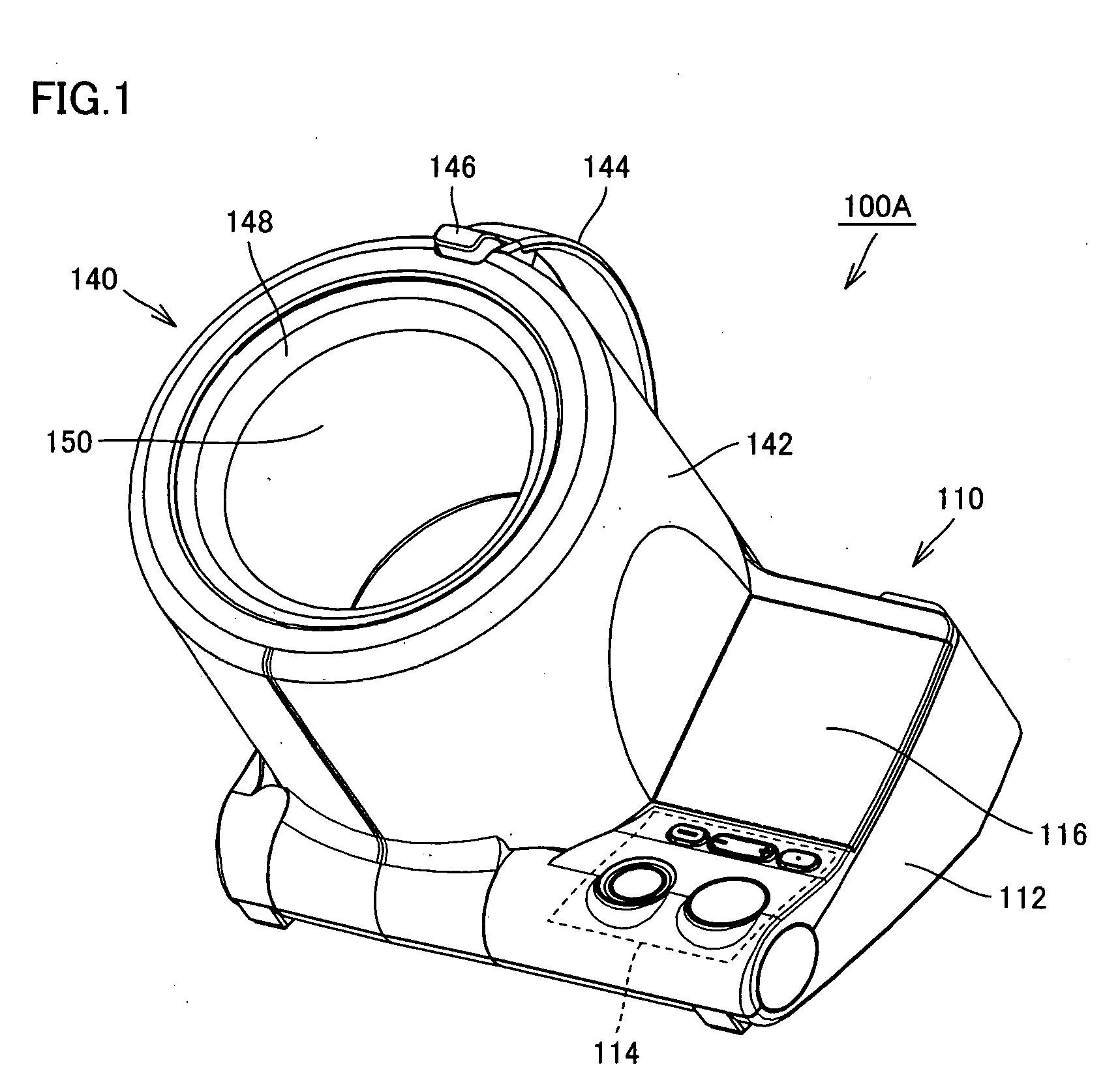
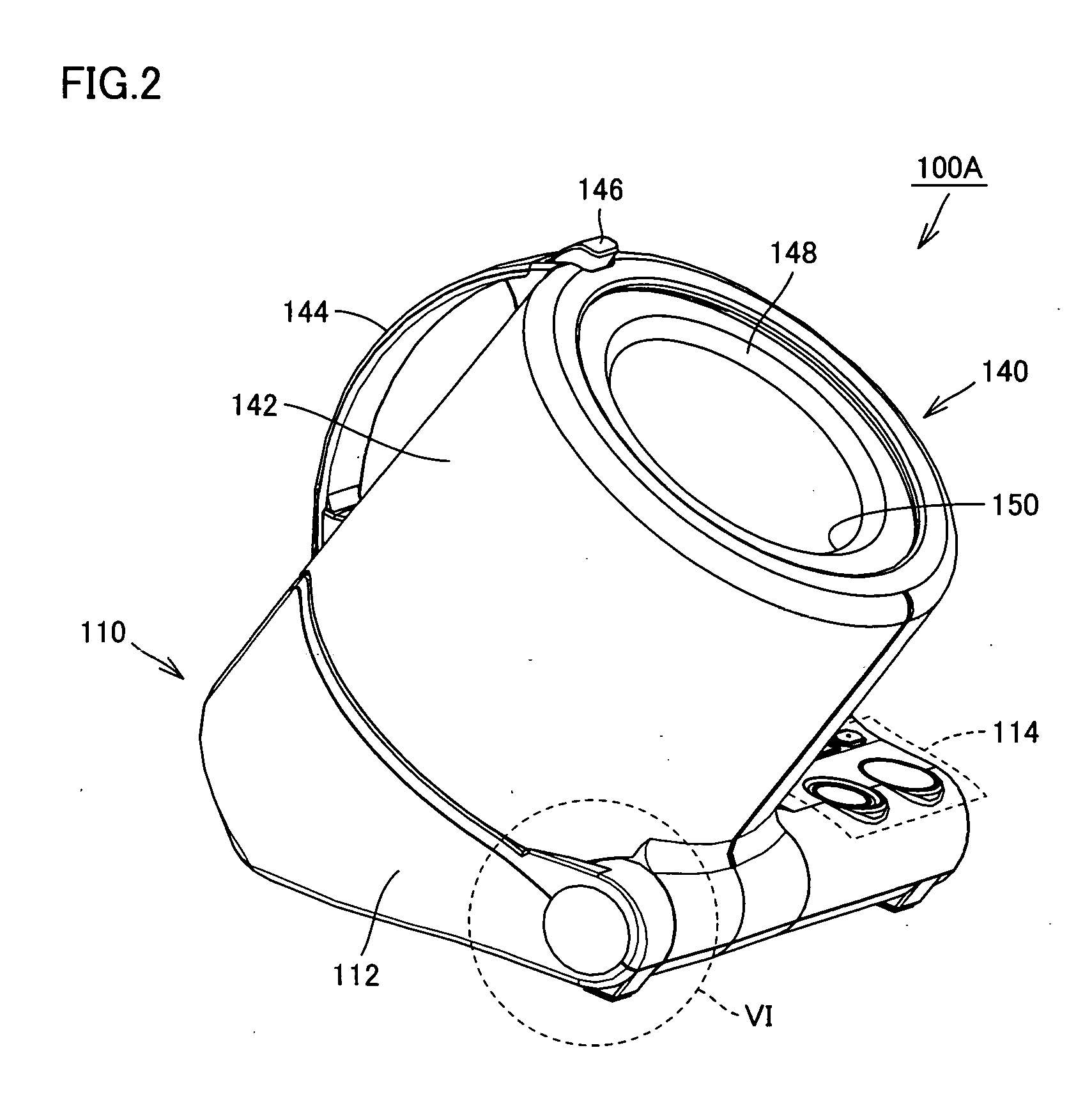
[0059] As shown in FIGS. 1 and 2, the blood pressure monitor 100A according to the present embodiment primarily includes a main unit 110 placed on a table or the like, and a living body insert portion 140 having a hollow opening 150 to which a portion of a living body (an upper arm in the case of blood pressure monitor 100A of the present embodiment) of a subject is inserted. Main unit 110 is covered with a casing for the main unit (hereinafter, referred to as the “main unit casing”) 112 that is a first enclosure, and living bo...

second embodiment

[0087] A blood pressure monitor according to the present embodiment is identical to that of the first embodiment in that it detects arterial pressure pulse waves by pressing an upper arm of a subject to measure a blood pressure value and also in that the cuff is wound around the upper arm automatically by an automatic cuff winding mechanism. Thus, the portions similar to those of the blood pressure monitor of the first embodiment are denoted by the same reference characters, and description thereof will not be repeated here.

[0088] In the blood pressure monitor of the present embodiment, the living body insert portion casing and the main unit casing are connected to each other by a pivot connection mechanism including a pivot, as in the blood pressure monitor of the first embodiment. The living body insert portion casing moves with respect to the main unit casing in a pivotable manner, for which a wide movable range is ensured such that the subject can readily insert the arm to appl...

third embodiment

[0107] Hereinafter, a configuration of the blood pressure monitor according to the third embodiment of the present invention and a posture for measurement when using the relevant blood pressure monitor will be described. The portions similar to those of blood pressure monitor 100A of the first embodiment are denoted by the same reference characters, and description thereof is not repeated here.

[0108] As shown in FIG. 23A, in the blood pressure monitor 100C of the present embodiment, main unit casing 112 and living body insert portion casing 142 are slidably connected by a slide connection mechanism. More specifically, the slide connection mechanism is formed, e.g., of a ridge 149 provided at the lower end of living body insert portion casing 142 with a prescribed radius of curvature, and a guide groove provided at the upper end of main unit casing 112 with a prescribed radius of curvature. Engagement of ridge 149 with the guide groove realizes the connection between living body ins...


PUM


Abstract

A blood pressure monitor includes a main unit casing placed on a table, a living body insert portion casing of an approximately cylindrical shape, positioned on the main unit casing in a non-use state and having a cuff arranged on its inner peripheral surface, the cuff having a hollow portion to which an upper arm of a subject is inserted, and a connection mechanism for connecting the living body insert portion casing with the main unit casing in a movable manner such that, upon application of the cuff to the subject, the living body insert portion casing can move to come closer to the subject than the main unit casing. Thus, a blood pressure monitor provided with an automatic cuff winding mechanism enabling measurement of blood pressure with high accuracy, not giving unnecessary pain to the subject, and allowing measurement with an unconstrained posture can be provided.

Description

BACKGROUND OF THE INVENTION [0001] 1. Field of the Invention [0002] The present invention relates to a blood pressure measuring device, and more particularly to a blood pressure measuring device provided with an automatic cuff winding mechanism for automatically winding a cuff around a living body. [0003] 2. Description of the Background Art [0004] To measure a blood pressure value, generally, a cuff provided with a living body pressing fluid bag for pressing an artery located within the living body is wound around the body surface, and arterial pressure pulse waves caused in the artery by inflation / deflation of the living body pressing fluid bag are detected to measure the blood pressure value. Here, the cuff refers to a band-shaped structure having a bladder, which can be wound around a portion of a living body, for use in measurement of arterial pressure of an upper limb, a lower limb or the like by introducing fluid such as gas or liquid into the bladder. Thus, the cuff represen...

Claims


Application Information

Patent Timeline
Patent Type & Authority Applications(United States)
IPC IPC(8): A61B5/022
CPCA61B5/02233
Inventor SANO, YOSHIHIKONAKANISHI, TAKEFUMITANAKA, TAKAHIDETANIGUCHI, MINORUINOUE, TOMONORINAKANISHI, HIROYASAWANOI, YUKIYA
Owner OMRON HEALTHCARE CO LTD
Why Eureka
Try Eureka