
Method and device for filtering body fluid

a filtering body fluid and filter technology, applied in blood vessels, prostheses, veterinary instruments, etc., can solve the problems of inability to achieve exceptional effectiveness in actual use, limited procedure, and prone to certain safety problems in embolizations

Inactive Publication Date: 2005-09-01
EV3
View PDF99 Cites 48 Cited by
  • Summary
  • Abstract
  • Description
  • Claims
  • Application Information

AI Technical Summary

Benefits of technology

The method enables reproducible, cost-effective production of intravascular devices that can be accurately positioned and deployed within the body, reducing the risk of thrombi re-entry into the bloodstream during retrieval and enhancing the safety and efficacy of medical procedures.

Problems solved by technology

In part due to the inability to precisely position the embolization agents, this procedure is often limited in its utility.
Such balloon embolizations are also prone to certain safety problems, though.
However, such filters generally have not proven to be exceptionally effective in actual use.
Such filters tend to be cumbersome to use and accurate deployment is problematic because if they are not properly seated in the vessel they can drift to a more distal site where they are likely to do more harm than good.
In addition, these filters are generally capable of only trapping relatively large thrombi and are not effective means for removing smaller embolic particles from the blood stream.
The problems with temporary filters, which are intended to be used only during a particular procedure then retracted with the thrombi trapped therein, are more pronounced.
Even if the trap does effectively capture the dislodged material, it has proven to be relatively difficult or complex to retract the trap back into the catheter through which it was delivered without simply dumping the trapped thrombi back into the blood stream, defeating the purpose of the temporary filter device.
Even if some of those devices have proven effective, they tend to be rather expensive and time-consuming to manufacture.
Not only does this take significant skilled manpower, and hence increase the costs of such devices, the fact that each item must be made by hand tends to make quality control more difficult.
This same difficulty and expense of manufacturing is not limited to such filters, but is experienced in many other intravascular devices as well.

Method used


Image

  • Method and device for filtering body fluid
  • Method and device for filtering body fluid
  • Method and device for filtering body fluid

Examples


Embodiment Construction

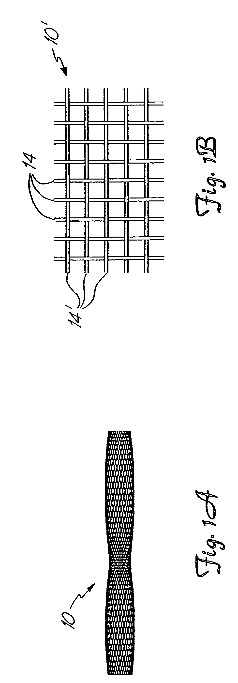
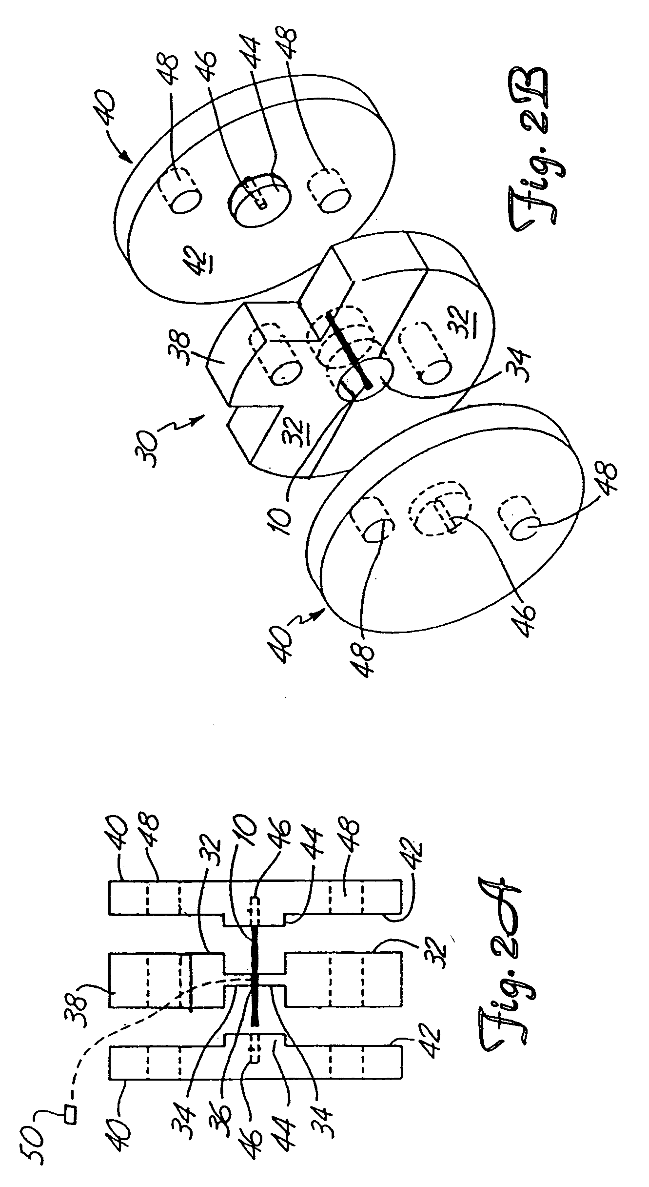
[0035] The present invention provides a reproducible, relatively inexpensive method of forming devices for use in channels in patients' bodies, such as vascular channels, urinary tracts, biliary ducts and the like, as well as devices which may be made via that method. In forming a medical device via the method of the invention, a metal fabric 10 is provided. The fabric is formed of a plurality of wire strands having a predetermined relative orientation between the strands. FIGS. 1A and 1B illustrate two examples of metal fabrics which are suitable for use in the method of the invention.

[0036] In the fabric of FIG. 1A, the metal strands define two sets of essentially parallel generally helical strands, with the strands of one set having a “hand”, i.e. a direction of rotation, opposite that of the other set. This defines a generally tubular fabric, known in the fabric industry as a tubular braid. Such tubular braids are well known in the fabric arts and find some applications in the ...


PUM


Abstract

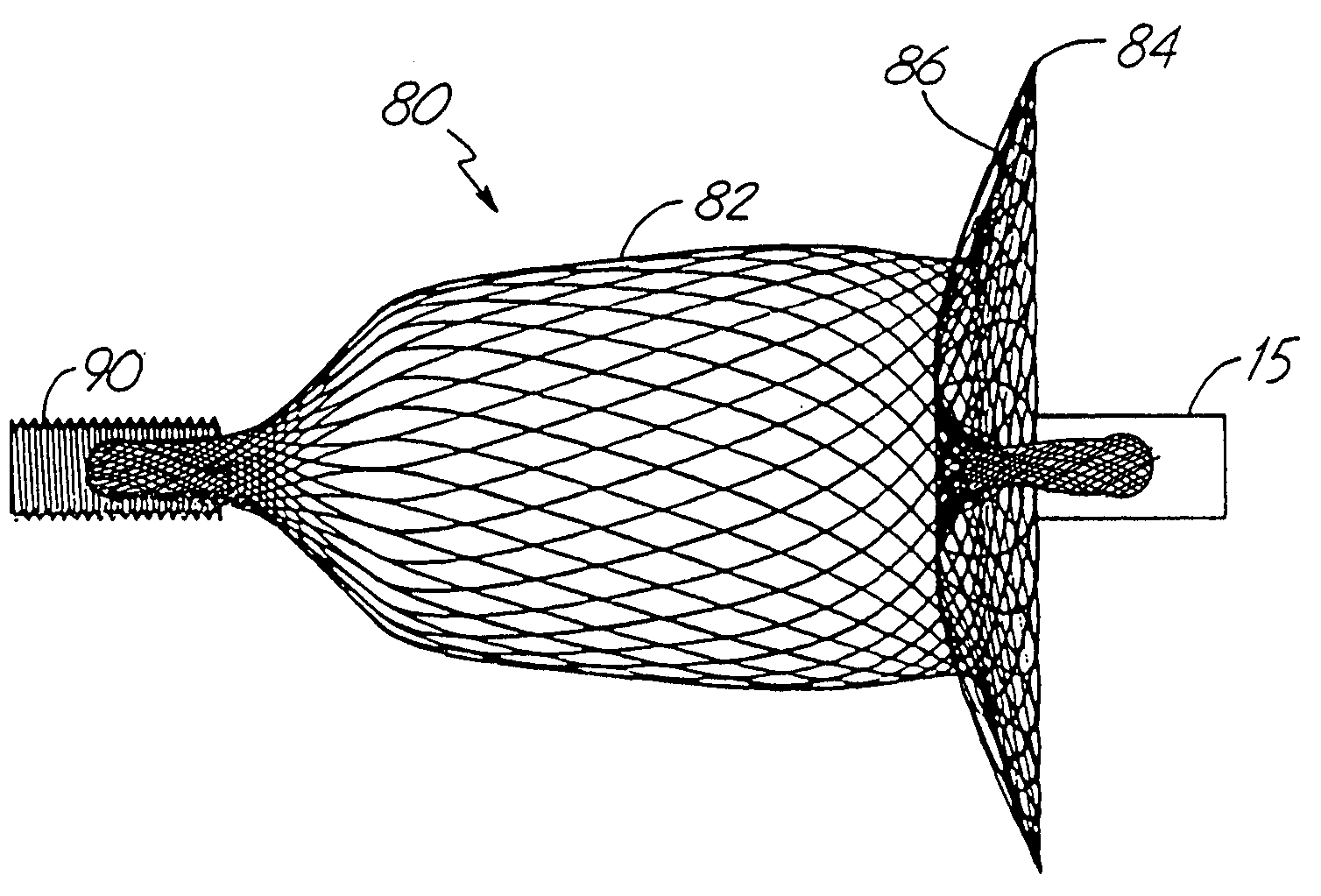
Medical devices for filtering fluids flowing through a lumen and a method of forming medical devices. The devices can be used in vascular channels, urinary tracts, biliary ducts and the like, and filter emboli and other debris generated at a treatment site.

Description

[0001] This application is a continuation of application U.S. Ser. No. 10 / 051,591, filed Jan. 18, 2002, which is a continuation of U.S. Ser. No. 08 / 748,066, filed Nov. 12, 1996, now U.S. Pat. No. 6,605,102, issued Aug. 12, 2003, which is a continuation of application Ser. No. 08 / 272,425, filed Jul. 8, 1994, now abandoned.FIELD OF THE INVENTION [0002] The present invention generally relates to intravascular devices for treating certain medical conditions and, more particularly, provides a method of forming intravascular devices and certain novel intravascular occlusion devices. The devices made in accordance with the invention are particularly well suited for delivery through a catheter or the like to a remote location in a patient's vascular system or in analogous vessels within a patient's body. BACKGROUND OF THE INVENTION [0003] A wide variety of intravascular devices are used in various medical procedures. Certain intravascular devices, such as catheters and guidewires, are gener...

Claims


Application Information

Patent Timeline
Patent Type & Authority Applications(United States)
IPC IPC(8): A61B17/00A61B17/12A61B17/22A61B17/221A61F2/01A61M29/00
CPCA61B17/12022A61F2230/008A61B17/12109A61B17/12136A61B17/12172A61B17/12177A61B17/221A61B2017/00526A61F2/01A61F2/013A61F2002/011B21F45/008A61F2002/016A61F2230/0006A61F2230/0067A61F2230/0069A61F2230/0078A61B17/12099A61F2/011A61F2/0105A61B17/0057A61B2017/00575A61B2017/00592A61B2017/00601A61B2017/0061A61B2017/00623
Inventor MAZZOCCHI, RUDYCLAUDE, TIMOTHYSEGERMARK, JAMES
Owner EV3
Learn More