
Mitral valve annuloplasty ring having a posterior bow

a technology of annuloplasty and mitral valve, which is applied in the field of medical devices, can solve the problems of increasing incidence, hospitalization and death, and the need for progressively harder pumping of blood in the left ventricl

Active Publication Date: 2005-09-01
EDWARDS LIFESCIENCES CORP
View PDF20 Cites 72 Cited by
  • Summary
  • Abstract
  • Description
  • Claims
  • Application Information

AI Technical Summary

Benefits of technology

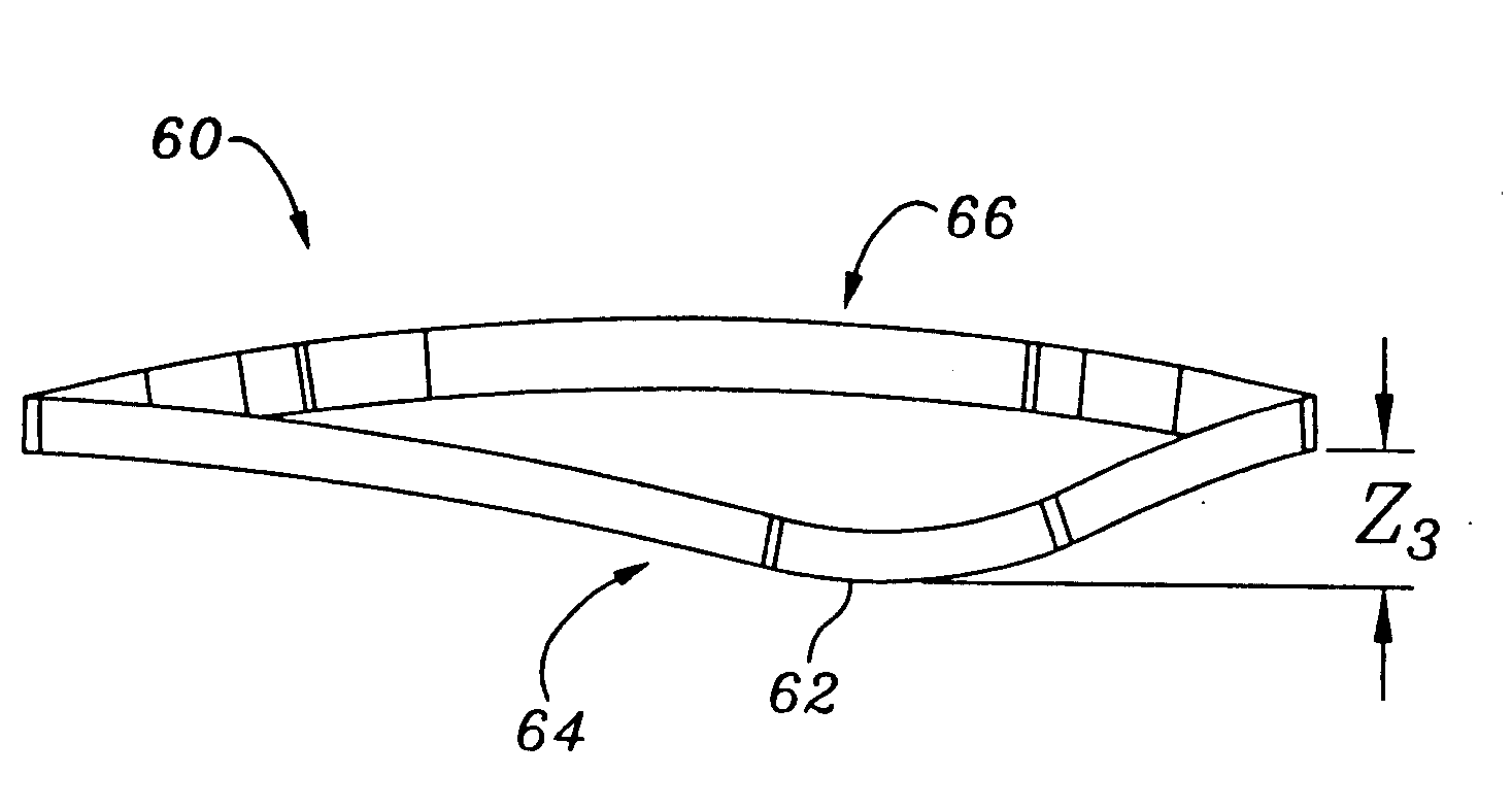
[0016] In plan view, as seen along the flow axis, the ring body preferably defines an oval shape with a major axis perpendicular to a minor axis, the minor axis bisecting both the anterior and posterior sections. Further, the bow in the posterior section may begin at symmetric locations across the minor axis that are spaced from the major axis around the ring body by an angle θ of between about 0-45°, more preferably about 30°.
[0017] The ring body may further include two upward bows on either side of the downward bow on the posterior s...

Problems solved by technology

In many developed countries, congestive heart failure is a leading cause of hospitalization and death, and its incidence is increasing.
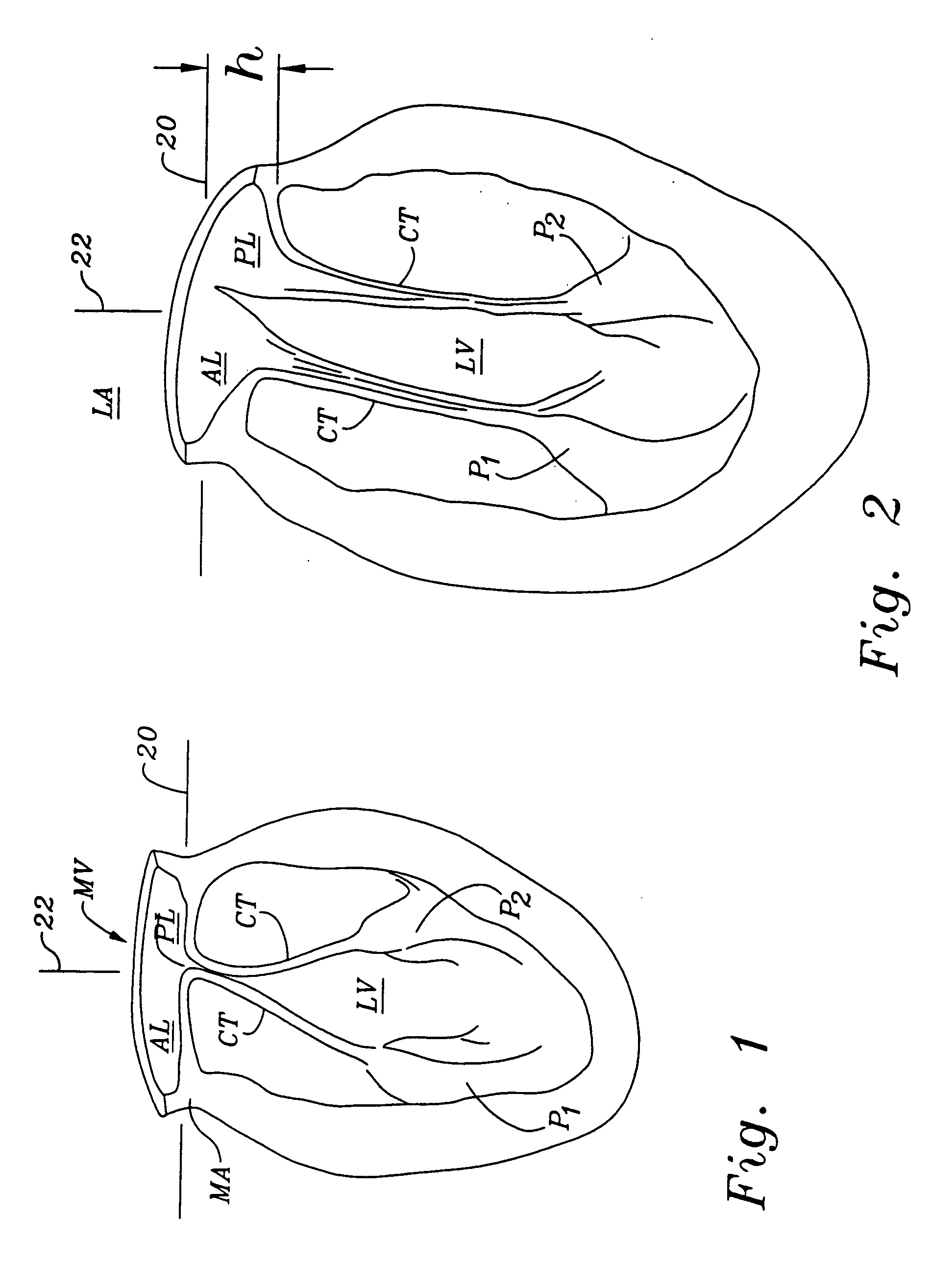
When imperfections in the mitral valve allows blood to flow backward into the left atrium, known as secondary mitral regurgitation, the left ventricle must pump progressively harder to circulate blood throughout the body, which in turn promotes congestive heart failure.
Heart transplantation is considered a standard treatment for select patients with severe congestive heart failure and end-stage heart disease, but only a small number of donor hearts are available and there are severe surgical risks for weaker patients.
Such rings would not be suitable for correcting a mitral valve deficiency.

Method used


Image

  • Mitral valve annuloplasty ring having a posterior bow
  • Mitral valve annuloplasty ring having a posterior bow
  • Mitral valve annuloplasty ring having a posterior bow

Examples


Embodiment Construction

[0031] The attached figures illustrate several exemplary embodiments of the annuloplasty ring of the present invention, which can be described as being continuous and having an anterior side, a posterior side and right and left sides. All of the sides are generally curvilinear with no specific demarcations to indicate abrupt transitions therebetween. Rather, smooth transitional sections between the adjacent sides provide curvilinear connections that give the ring a generally rounded (e.g., oval) configuration.

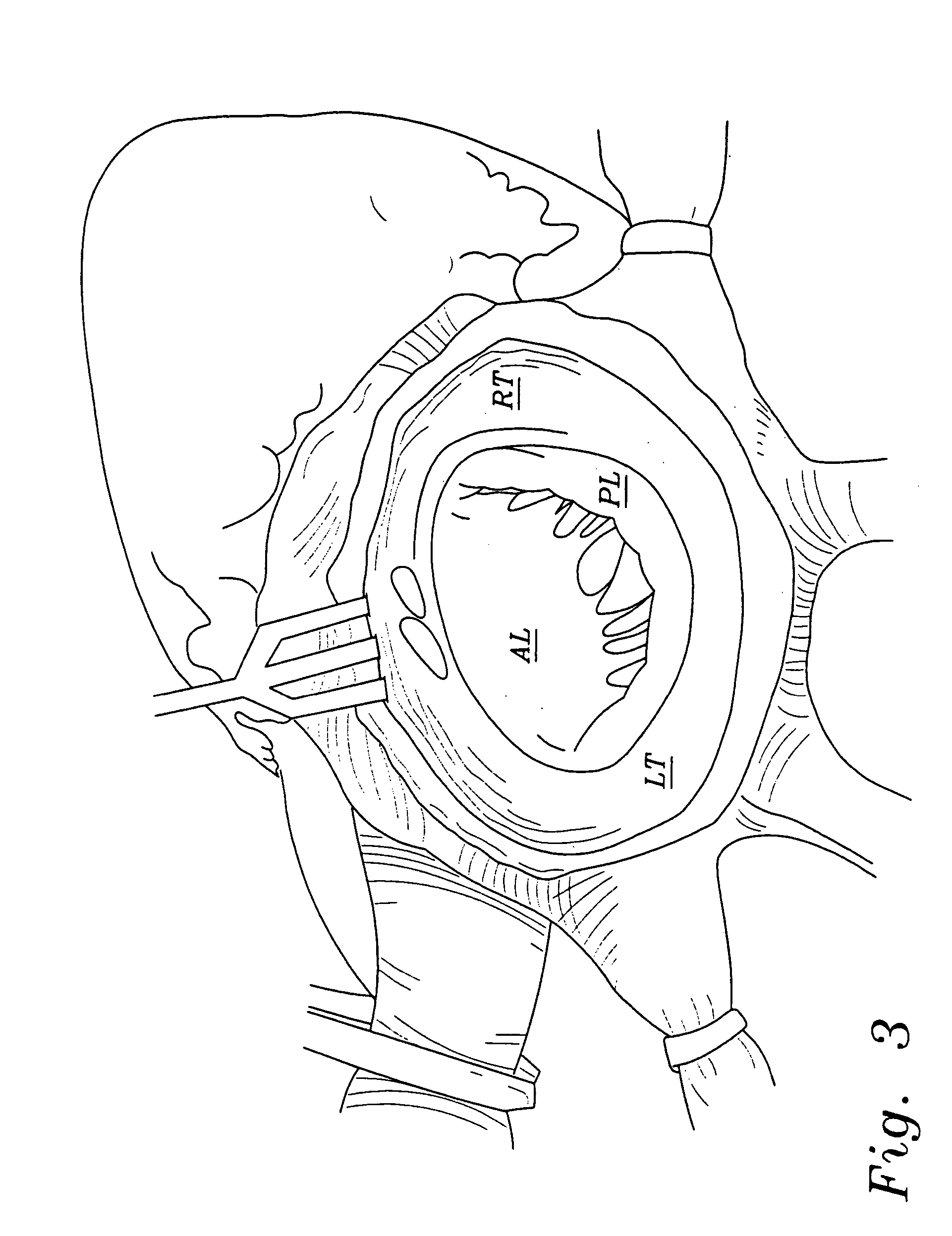
[0032] An exemplary annuloplasty ring 30 of the present invention is shown in FIG. 4 implanted around a mitral annulus MA. As described above, the mitral annulus has an anterior leaflet AL and a posterior leaflet PL. When the ring 30 is implanted, the leaflets are brought closer together and supported so that they meet at a coaptation surface 32. The ring 30 thus corrects the problem of functional mitral regurgitation.

[0033] The ring 30 has an oval or somewhat D-shaped config...


PUM


Abstract

A mitral heart valve annuloplasty ring having a posterior bow that conforms to an abnormal posterior aspect of the mitral annulus. The ring may be generally oval having a major axis and a minor axis, wherein the posterior bow may be centered along the minor axis or offset in a posterior section. The ring may be substantially planar, or may include upward bows on either side of the posterior bow. The ring may include a ring body surrounded by a suture-permeable fabric sheath, and the ring body may be formed of a plurality of concentric ring elements. The ring is semi-rigid and the posterior bow is stiff enough to withstand deformation once implanted and subjected to normal physiologic stresses. The ring elements may be bands of semi-rigid material. A method of repairing an abnormal mitral heart valve annulus having a depressed posterior aspect includes providing a ring with a posterior bow and implanting the ring to support the annulus without unduly stressing the attachment sutures.

Description

RELATED APPLICATIONS [0001] The present application is a continuation-in-part of Ser. No. 10 / 192,516, filed Jul. 8, 2002, which is incorporated herein by reference in its entirety.FIELD OF THE INVENTION [0002] The present invention relates generally to medical devices, specifically to an annuloplasty ring and related procedure for surgically reconstructing the mitral valve annulus of a patient's heart. More specifically, this invention relates to a mitral valve repair device and corresponding technique that conforms to an abnormal annulus in the pathology encountered with functional mitral regurgitation having a posterior aspect depressed below the anterior aspect. BACKGROUND OF THE INVENTION [0003] In the anatomy of the human heart, the left atrium receives oxygenated blood from the lungs through the pulmonary vein. The mitral valve separates the left atrium from the left ventricle. During diastole, as the contraction triggered by the sinoatrial node progresses through the atria, o...

Claims


Application Information

Patent Timeline
IPC IPC(8): A61F2/00A61F2/24
CPCA61F2/2445A61F2250/0018A61F2/2448
Inventor MCCARTHY, PATRICK
Owner EDWARDS LIFESCIENCES CORP
Learn More