Disaster recovery processing method and apparatus and storage unit for the same

a technology of disaster recovery and processing method, applied in the field of disaster recovery system, can solve the problems of heavy load on the network between the host computer, unnecessary input and output operations, and inability to recover data, so as to reduce the amount of data to be transmitted between the primary and secondary host computers and/or between the primary and secondary storage systems, and reduce the load of input/output processing

Active Publication Date: 2005-09-01
HITACHI LTD
View PDF39 Cites 20 Cited by
  • Summary
  • Abstract
  • Description
  • Claims
  • Application Information

AI Technical Summary

Problems solved by technology

However, since the database blocks thus modified also include records not modified, unnecessary input and output operations take place.
This leads to a problem that a heavy load is imposed on the input and output processing between the host computer and the storage system.
This leads to a problem of a load on a network between the host computer of the primary system and that of the secondary system.
Therefore, records not updated are repeatedly copied and there arises a problem of a high input / output load between the storage systems.

Method used


Image

  • Disaster recovery processing method and apparatus and storage unit for the same
  • Disaster recovery processing method and apparatus and storage unit for the same
  • Disaster recovery processing method and apparatus and storage unit for the same

Examples


first embodiment

[0042] Next, description will be given of a first embodiment of a disaster recovery system in which a database in a magnetic disk device of a secondary storage system is updated using log information indicating the contents of database processing executed by a primary host computer.

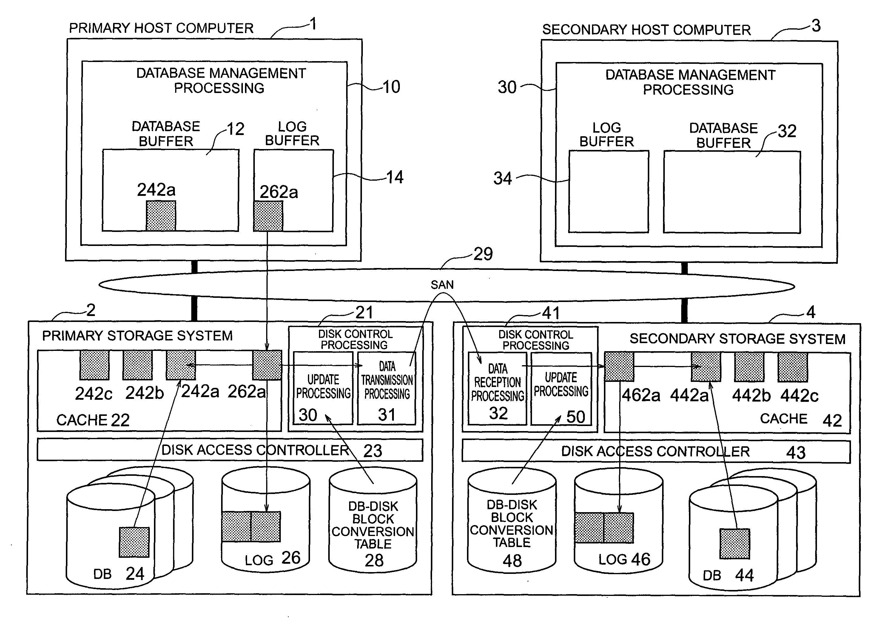
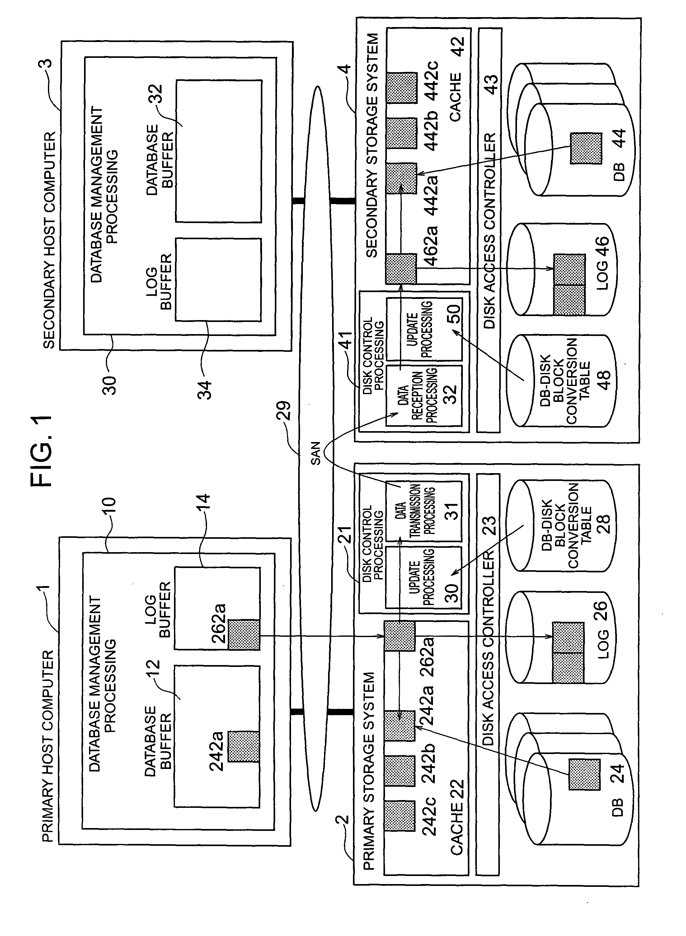
[0043]FIG. 1 shows a system configuration of the discovery system of the embodiment. As shown in FIG. 1, a primary host computer 1 of the embodiment includes a database management processing portion 10. The portion 10 is a processing portion in which when it is required to force the contents of a database (DB) buffer 12 of the primary host computer in a magnetic disk device of a storage system 2 as a primary storage system, a write request of a log block 262a which is log information indicating the contents of database processing executed for the database buffer 12 is sent from the primary host computer 1 to the primary storage system 2. If the database buffer 12 does not include data as an access object...

second embodiment

[0102] Description will now be given of a second embodiment of the disaster recovery system executing the update processing using particular log information, namely, log information of a committed transaction.

[0103] In the log tracking processing of the first embodiment, all log records are forced in the pertinent database blocks. However, in conjunction with the second embodiment, description will be given of another method of executing the log tracking processing by referring to FIGS. 9 to 11. In the following paragraphs, the log tracking processing of the primary storage system 2 will be described. However, it is assumed that the log tracking processing of the secondary storage system 4 is similarly executed.

[0104]FIG. 9 shows an example of results of log analysis for each transaction using all log records of the log blocks in the log tracking processing according to the embodiment. As shown in FIG. 9, the log block 262a is analyzed and a log buffer 264 is first reserved in a s...

third embodiment

[0122] Next, description will be given of a third embodiment of the disaster recovery system in which the data items of the database areas are concurrently updated for respective physical devices corresponding to the data items of the database areas.

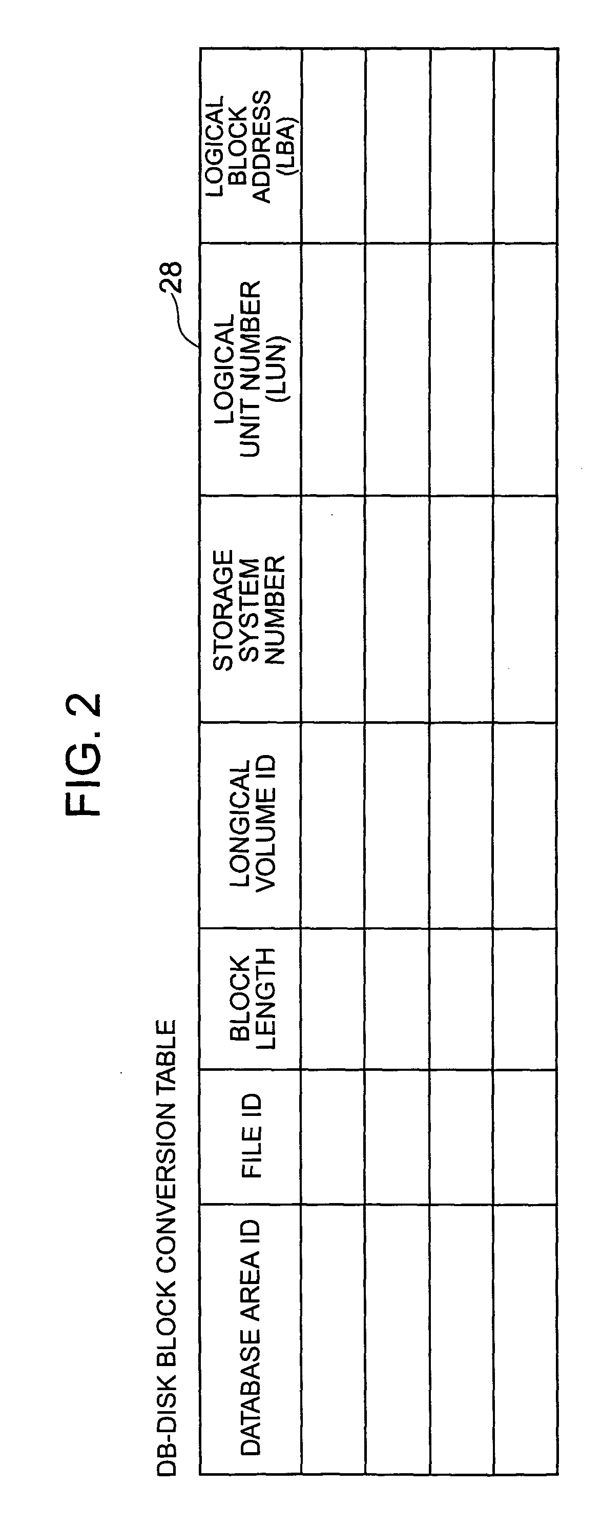
[0123]FIG. 12 shows a general configuration of the embodiment of the disaster recovery system. The processing of the embodiment can be commonly implemented for the first and second embodiments. That is, in the log tracking processing of FIG. 6 for the first embodiment and that of FIG. 11 for the second embodiment, the primary storage system 2 obtains a drive number of a physical drive using the database-disk block conversion table 28 according to the database area identifier, the file identifier, and the page number of the database block and then distributes the processing to mutually different processors for the respective drives to execute the processing. As a result, the storage system 2 concurrently executes the WRITE processing in ...


PUM


Abstract

Judgement is made to determine whether or not an access request from a host computer is a write request and whether or not the contents of the write request are log information indicating contents of database processing executed in a buffer by the host computer. When the contents of the write request are the log information, position information indicated in the log information is converted into physical position information in a primary storage system using a conversion table indicating a correspondence between logical position information recognized by the host computer and physical position information in the primary storage system. According to the contents of the log information, data is updated in a database area of the primary storage system represented by the physical position information converted using the conversion table. The access request is sent to a secondary storage system.

Description

CROSS-REFERENCE TO RELATED APPLICATION [0001] This invention relates to a patent application Ser. No. ______ entitled DATABASE PROCESSING METHOD AND SYSTEM USING LOG INFORMATION, PROCESSING PROGRAM THEREOF, AND STORAGE UNIT FOR EXECUTION THEREOF filed by N. KAWAMURA et al. on ______ claiming foreign priority under 35 U.S.C. Section 119 of Japanese Patent Application No. 2002-368688.BACKGROUND OF THE INVENTION [0002] The present invention relates to a disaster recovery system in which at occurrence of a failure in a primary database processing system, the system continues execution of the data processing by replacing the failed database processing system with a secondary database processing system, and in particular, to a technology effectively applicable to a disaster recovery system in which using log information indicating contents of database processing executed on a database buffer of a primary host computer, a database is updated in a magnetic disk device of a secondary storage...

Claims


Application Information

Patent Timeline
Patent Type & Authority Applications(United States)
IPC IPC(8): G06F3/06G06F12/00G06F17/30
CPCG06F11/2048Y10S707/99955G06F11/2097G06F11/2092G06F11/1471
Inventor KITSUREGAWA, MASARUKAWAMURA, NOBUOMASAI, KAZUO
Owner HITACHI LTD
Why Eureka
Try Eureka