Test procedure for determining steering rack rattle

a steering rack and test procedure technology, applied in the direction of mechanical measuring arrangements, instruments, nuclear elements, etc., can solve the problems of increased clearance between components, wear at the interface of the rack with the pinion and in the system, and rattles inside the steering rack that can be heard by the vehicle occupants, so as to reduce the cost and the amount of data

Active Publication Date: 2010-06-22
GM GLOBAL TECH OPERATIONS LLC
View PDF1 Cites 7 Cited by
  • Summary
  • Abstract
  • Description
  • Claims
  • Application Information

AI Technical Summary

Benefits of technology

[0006]An advantage of an embodiment is that a lab test metric is created that can determine steering system performance in regard to rack rattle in an objective, rather than subjective, manner. This metric allows for determining a maximum acceptable noise level for steering system internal rattles in a lab test and testing steering systems to determine if they meet the acceptable noise levels. Moreover, by detecting the levels in a steering system itself, rather than when operating a vehicle, the amount of data, especially extraneous noise data that otherwise might come from other components of the vehicle, is significantly reduced. And, being an objective lab test at the component level, the rattle test can produce repeatable data, allowing accurate testing for many different designs of rack and pinion steering systems to be tested. Moreover, the tests can be conducted at the vehicle manufacturer's facilities, or at a supplier's facilities, producing consistent results.
[0007]The component level test in a lab, then, may allow rattles to be engineered out of steering systems prior to building full vehicles for testing. And, it may allow for an ability to differentiate between different suppliers of steering systems based on propensity for rattle, thus allowing for the propensity for rattle to be a factor in choosing a supplier. Such early engineering information may reduce the likelihood of having to replace steering system components in vehicles, thus reducing costs. And, vehicle testing on different road surface types may also be employed to confirm that rattles have been engineered out of the steering system.

Problems solved by technology

In conventional rack and pinion steering systems for vehicles, wear occurs in the rack and pinion system that results in increased clearance between components.
Typically, the wear occurs at the interface of the rack with the pinion and in the system that preloads the rack to the pinion.
The clearance resulting from the wear then results in rattles inside the steering rack that can be heard by the vehicle occupants, typically when they are driving over rough roads.
The wear may actually occur early in a vehicle's life, costing a great deal to replace a steering rack or steering column, and possibly reducing a vehicle owner's satisfaction with the vehicle overall.
Occasionally, depending on the design or initial settings, some racks and columns even rattle when new.
But there is generally too much extraneous noise in these recordings to allow for objective analysis based solely on these recordings.
Consequently, the typical steering rack rattle performance ratings are determined subjectively on random road test events, making repeatability very difficult.
Moreover, since this is done on a vehicle level test, other components in the vehicle can make noise during the test that make it even more difficult to correctly determine the noise levels of the steering system separate from these other noises.

Method used


Image

  • Test procedure for determining steering rack rattle
  • Test procedure for determining steering rack rattle
  • Test procedure for determining steering rack rattle

Examples


Embodiment Construction

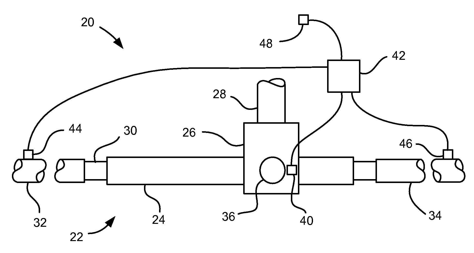
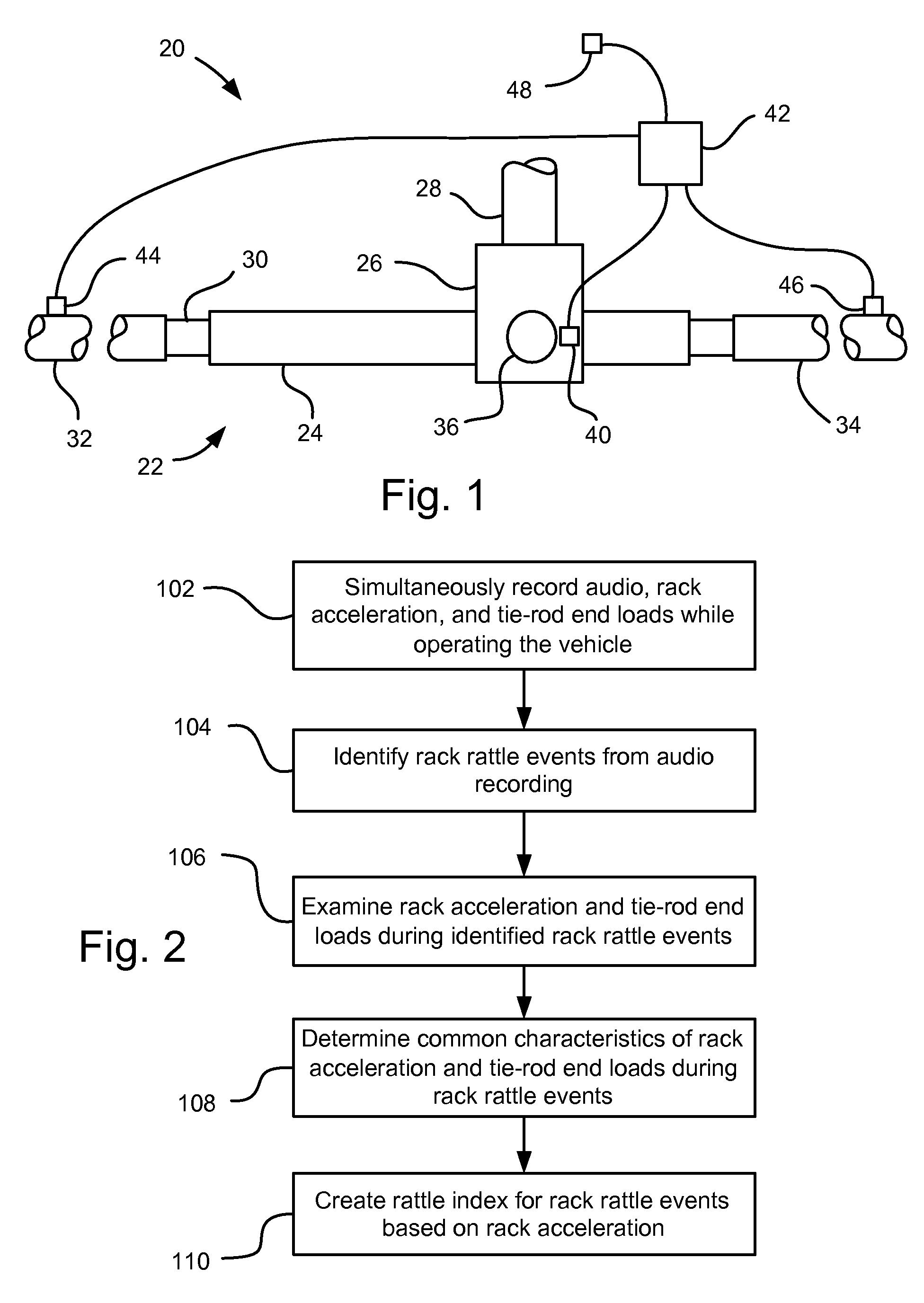
[0012]Referring to FIG. 1, a vehicle, indicated generally at 20, is shown. The vehicle 20 includes a steering assembly 22, which includes a steering rack housing 24. A gear housing 26 receives a steering shaft 28. The steering shaft 28 may have a conventional pinion gear (not shown) that mates with a conventional rack gear (not shown) on a rack 30 that slides telescopically back and forth in the steering rack housing 24. An adjuster plug 36 may be employed to bias the pinion gear and rack gear into contact with each other to limit rattle between the two. The rack 30 engages a right side tie-rod 32 at a first end and a left side tie-rod 34 at an opposite end. The right and left side tie-rods 32, 34 engage other steering assembly components (not shown) in a conventional fashion for pivoting vehicle wheels (not shown). The components discussed above may be essentially conventional, if so desired, and so will not be discussed further herein. Also, this steering assembly 22 may be mounte...


PUM


Abstract

A method of determining steering rack rattle propensity of a rack and pinion steering assembly may comprise: simultaneously recording audio, and measuring acceleration of a rack, and right and left side tie-rod end loads; identifying rack rattle events from the audio recording; determining common characteristics of the measured rack acceleration and tie-rod end loads during the identified rack rattle events; creating a rack rattle index level; applying a predetermined force profile to a test rack and pinion steering assembly; measuring a test acceleration on the test rack and pinion steering assembly; calculating a test RMS level in a test frequency range using a test time constant; determining a rack rattle index value from the calculated test RMS level; and comparing the rack rattle index value to the rack rattle index level.

Description

BACKGROUND OF INVENTION[0001]The present invention relates generally to undesirable rattle that sometimes occurs in steering racks of vehicle steering systems, and more particularly to a test procedure for being able to determine a propensity for rack rattle in a vehicle from a lab test.[0002]In conventional rack and pinion steering systems for vehicles, wear occurs in the rack and pinion system that results in increased clearance between components. Typically, the wear occurs at the interface of the rack with the pinion and in the system that preloads the rack to the pinion. The clearance resulting from the wear then results in rattles inside the steering rack that can be heard by the vehicle occupants, typically when they are driving over rough roads. The wear may actually occur early in a vehicle's life, costing a great deal to replace a steering rack or steering column, and possibly reducing a vehicle owner's satisfaction with the vehicle overall. Occasionally, depending on the ...

Claims


Application Information

Patent Timeline
Patent Type & Authority Patents(United States)
IPC IPC(8): G06F11/30B62D5/06B62D5/04
CPCG01M7/027
Inventor LEMONT, JR., CHARLES J.LOPEZ, JOSE M.POMERVILLE, DAVID C.KLOESS, SCOTT R.BRINES, ROBERT S.TAHNOOSE, MARC J.MALLARD, DARRIN S.
Owner GM GLOBAL TECH OPERATIONS LLC
Why Eureka
Try Eureka