Fleece laying device

a technology of fleece and laying device, which is applied in the direction of lap-winding device, fibre treatment, textiles and paper, etc., can solve the problems of reducing web quality and distorting a sensitive fiber web

Inactive Publication Date: 2005-09-08
DILO MASCHF OSKAR
View PDF9 Cites 19 Cited by
  • Summary
  • Abstract
  • Description
  • Claims
  • Application Information

AI Technical Summary

Benefits of technology

[0018] In certain embodiments, the common frame is movably held by a pendulum. Other fo...

Problems solved by technology

Thus a drawing movement may distort a sensitive fiber web within this unsupported region.
Because of this, the we...

Method used


Image

  • Fleece laying device
  • Fleece laying device
  • Fleece laying device

Examples


first embodiment

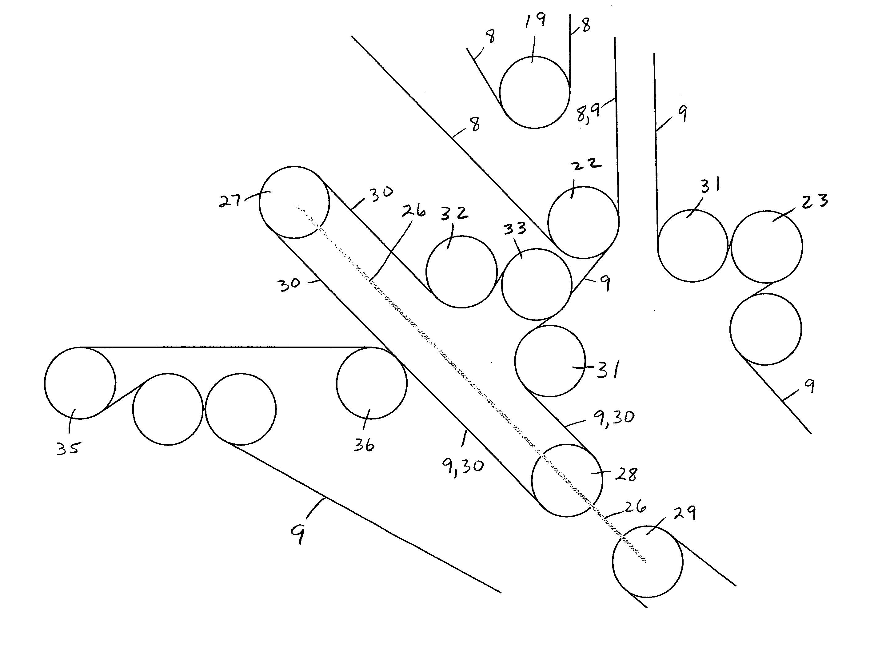
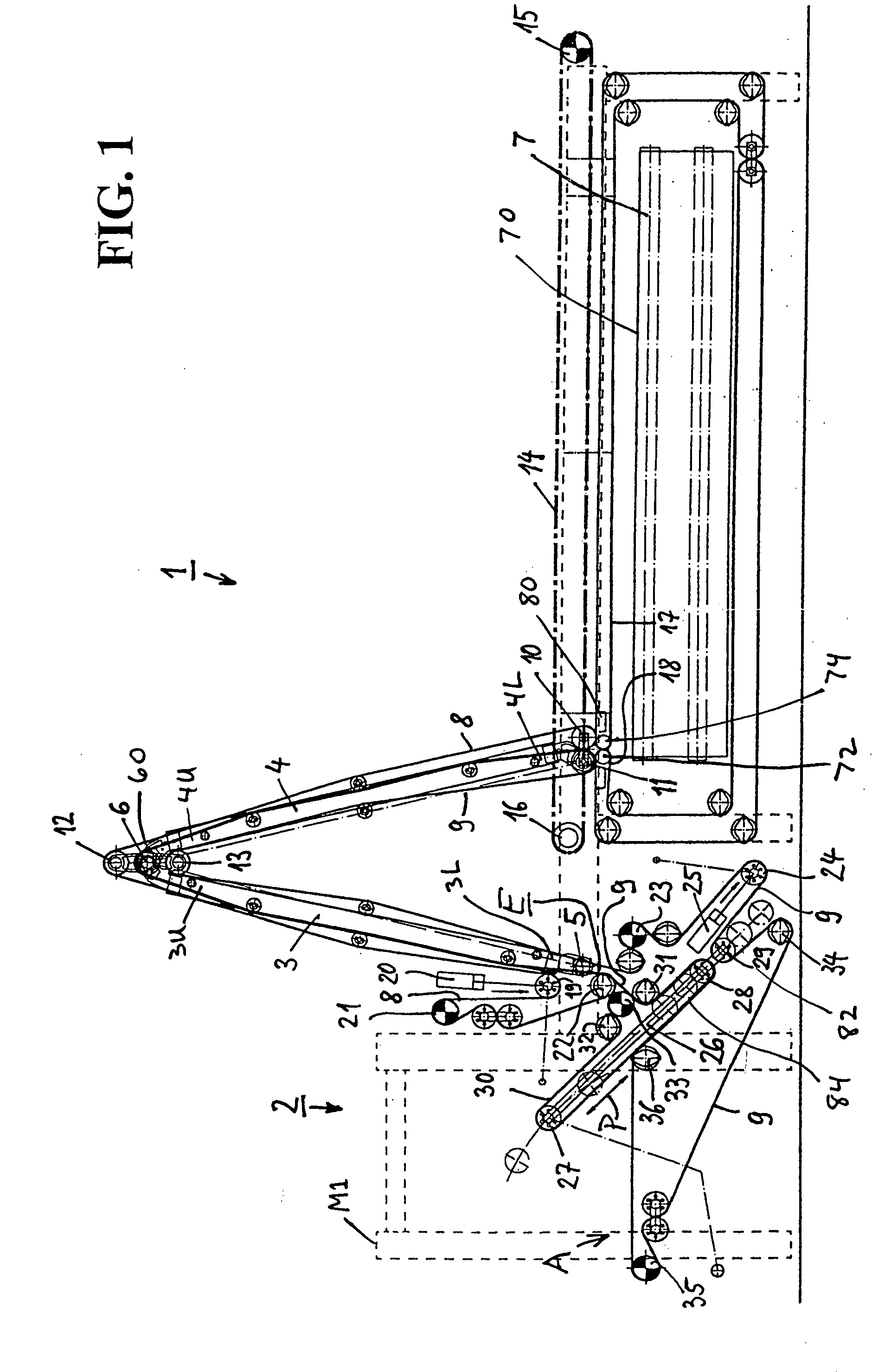
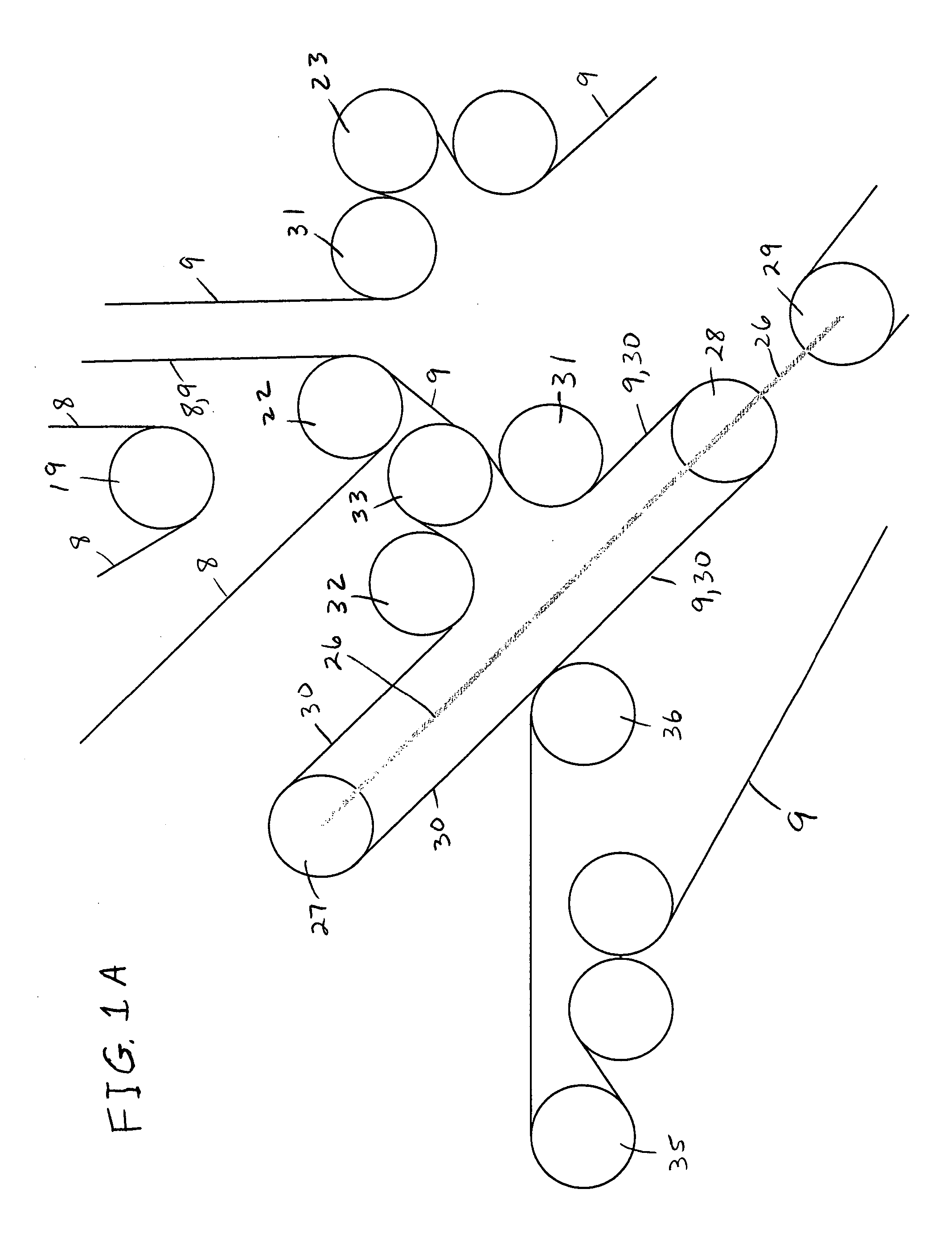
[0039] Whereas FIG. 1 shows cross arms 3 and 4 of cross lapper 1 in retracted positions, FIG. 2 shows arms 3 and 4 in extended positions. The extension of arms 3 and 4 result in a variation of the looping angles of transport belts 8 and 9 at the deflecting rollers situated at the hinges of the arms. Some of these variations compensate one another, however, and for some other of these variations, there is no automatic compensation. The necessary balance is created by tensioning rollers 19 and 24 located in the running paths of transport belts 8 and 9 and by adapted rollers 19 and 24 to comply with the tension existent in their respective transport belts. A detailed explanation of this situation is presented with reference to the embodiment illustrated in FIGS. 3 and 4, the teaching of which is also applicable in the first embodiment shown in FIGS. 1 and 2.

second embodiment

[0040] the invention is described with reference to FIGS. 3 and 4. Elements which are similar to or the same as those of the first embodiment are provided with the same reference numerals.

[0041]FIG. 3 shows cross lapper 1 having supply arm 3 and layering arm 4 which are pivotably connected with one another and are mounted as in the embodiment of FIG. 1. Layering arm 4 is movably guided above output conveyor 7 by means of a toothed belt drive system 14, 15 and 16. A cover belt 17′ is connected to lower end 4L of layering arm 4. Cover belt 17′ is guided by way of a plurality of deflecting rollers and extends over output conveyor 7 transversely thereto to avoid air turbulence that may be caused by the movement of layering arm 4 from affecting the fleece formed on output conveyor 7.

[0042] A variable-volume fiber web buffering apparatus 2 is located to the left side of cross lapper 1. Web buffering apparatus 2 comprises transport belts 8 and 9, each of which run through web buffering ap...


PUM


Abstract

A non-woven fiber web laying apparatus including (1) a camel back cross lapper having a supply arm, a layering arm connected thereto, and two delivery transport belts guided in juxtaposed fashion from an infeed zone to a lower end of the layering arm and (2) an upstream web buffering apparatus adapted to hold a web between two take-up transport belts at least one of which is one of the two delivery transport belts, the apparatus sandwiching the web substantially the entire path from the take-up site to the layering-arm lower end. While at least one of the two take-up transport belts of the web buffering apparatus is one of the delivery transport belts of the cross lapper, in one embodiment both of the take-up transport belts are the delivery transport belts. In another embodiment, only one of the take-up transport belts is a delivery transport belt, the other being a pressure belt operating only within the web buffering apparatus.

Description

RELATED APPLICATIONS [0001] This application claims the benefit of: EP 04 005 460.3, filed on Mar. 8, 2004; EP 04 008 051.7, filed on Apr. 2, 2004; and EP 04 015 488.2, filed Jul. 7, 2004. The contents of these applications are incorporated herein.FIELD OF THE INVENTION [0002] This invention is related to the field of producing non-woven fabric or fleece made from fiber material. More particularly, the invention relates to machinery known as a cross lapper. BACKGROUND OF THE INVENTION [0003] U.S. Pat. No. 5,590,442 describes equipment for producing non-woven fabric, or fleece, made of fiber material. In this known fleece laying equipment, the cross lapper is a so-called flat cross lapper having an upper carriage and a layering carriage, each of which is provided with deflection rolls over which first and second endless transport belts conveying a non-woven fiber web are passed. These transport belts define a path length between the carriages. Within the path length, the fiber web is...

Claims


Application Information

Patent Timeline
IPC IPC(8): D01G25/00
CPCD04H1/74D01G25/00
Inventor LEGER, JOACHIM
Owner DILO MASCHF OSKAR
Why Eureka
Try Eureka