Control of heat exchanger operation

a technology of heat exchanger and control mechanism, which is applied in the field of heat exchangers, can solve the problems that the control mechanism for such operation has not addressed both energy saving and water saving, and achieve the effect of minimizing energy use and water us

Active Publication Date: 2005-09-08
BALTIMORE AIRCOIL CO INC +1
View PDF5 Cites 6 Cited by
  • Summary
  • Abstract
  • Description
  • Claims
  • Application Information

AI Technical Summary

Benefits of technology

[0007] It is another object of the present invention to provide an operating method for the efficient operation of a combined evaporative and non-evaporative heat exchanger wherein energy usage and water usage are minimized while meeting the heat reject

Problems solved by technology

Such combined evaporative and non-evaporative heat exchangers consume energy in the form of electricity for fan and pump operation and water

Method used


Image

  • Control of heat exchanger operation
  • Control of heat exchanger operation
  • Control of heat exchanger operation

Examples


Embodiment Construction

[0024] The following detailed description is of the best currently contemplated modes of carrying out the invention. The description is not to be taken in a limiting sense, but is made merely for the purpose of illustrating the general principles of the invention, since the scope of the invention is best defined by the appended claims.

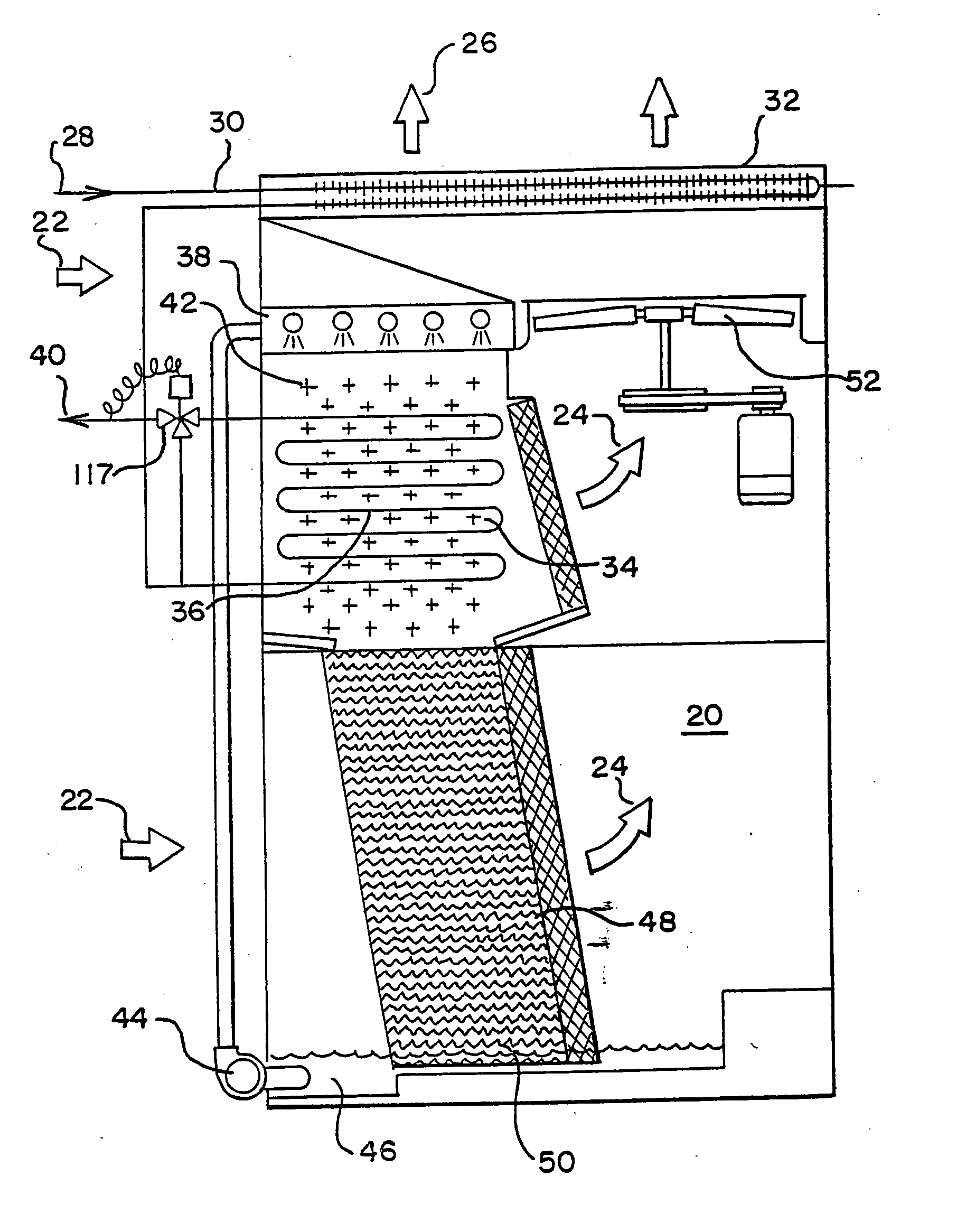
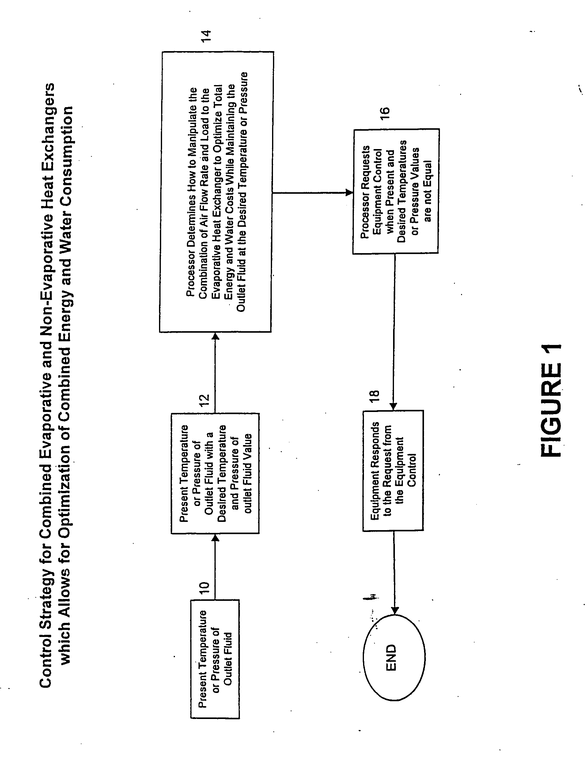
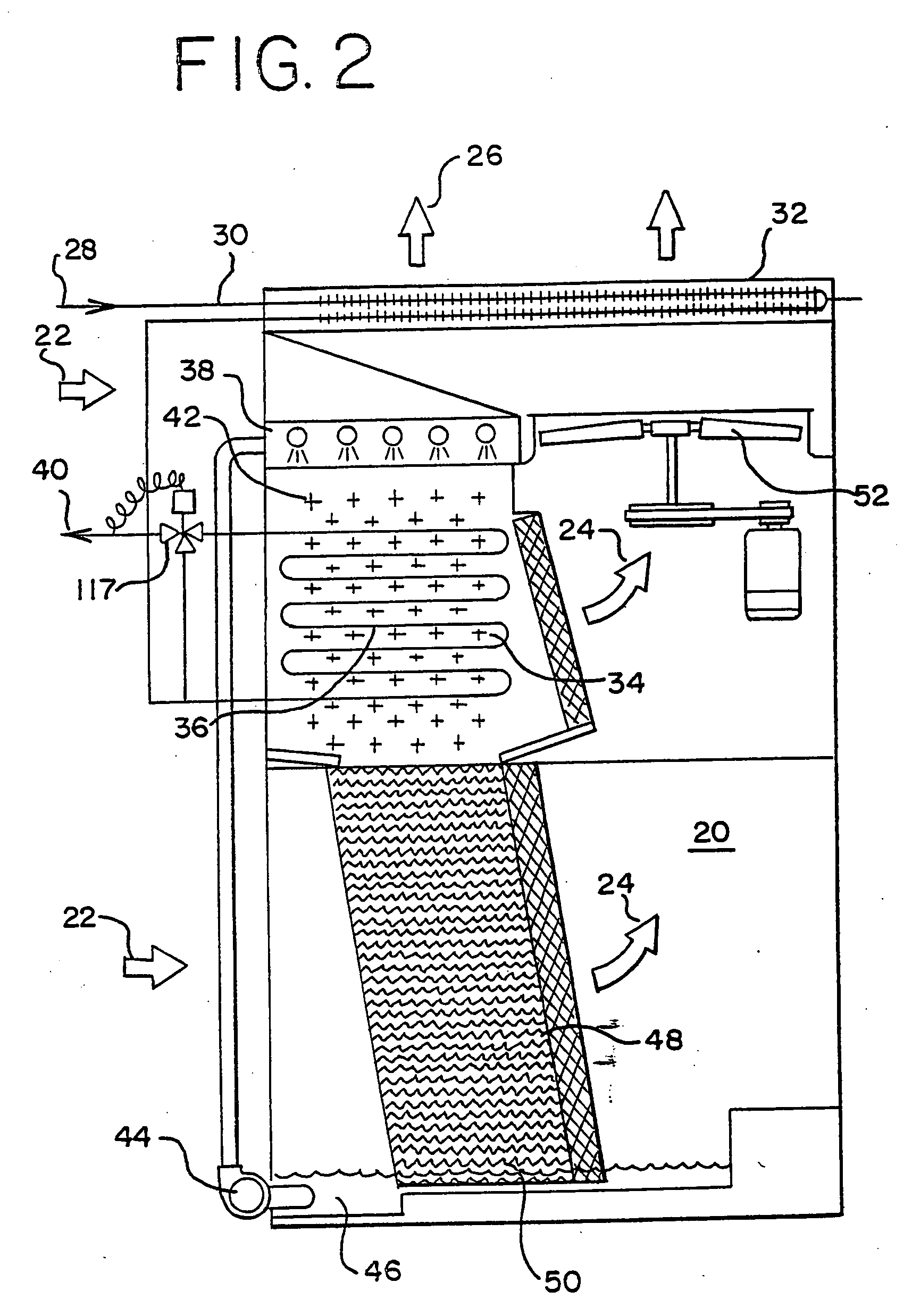
[0025] Referring now to FIG. 1 of the drawings shown is a flow chart of one embodiment of the present invention providing a temperature or pressure of an outlet fluid 10. A processor compares the present temperature or pressure of the outlet fluid with a desired temperature or pressure of the outlet fluid 12. The processor then determines how to manipulate the combination of air flowrate and load to an evaporative heat exchanger to optimize total energy and water costs while maintaining the outlet fluid at the desired temperature or pressure 14. Next the processor sends a request to an equipment control when present and desired temperature or pressure...


PUM


Abstract

A method of controlling the operation of a heat exchanger with evaporative and non-evaporative sections. The method includes the following steps: providing desired values of temperature or pressure; comparing present values of temperature or pressure to the desired values of temperature and pressure; and manipulating an air flowrate to the heat exchanger and load to the evaporative heat exchanger to optimize total energy and water costs while maintaining an outlet fluid at the desired temperature or pressure.

Description

BACKGROUND OF INVENTION [0001] The present invention relates to heat exchangers and, more particularly, to combine evaporative and non-evaporative heat exchangers. The evaporative section of the heat exchanger may have both a direct and indirect portion. [0002] Waste heat from industrial processes such as condensers or heat exchangers may itself be released to the atmosphere by non-evaporative or so called dry heat exchangers. In such non-evaporative heat exchanger and air stream is in indirect contact with a process fluid stream. In a close system, the process fluid stream is enclosed so that there is no direct contact between the air stream and the process fluid stream. The enclosing structure is usually a coil of tubes. Heat is exchanged as an air stream is passed over the coil structure enclosing the process fluid stream. [0003] Waste heat may also be rejected to the atmosphere by evaporative heat exchangers which offer significant process efficiency improvements over non-evapor...

Claims


Application Information

Patent Timeline
IPC IPC(8): F28D5/02F28F27/00
CPCF28C1/14F28C2001/145F28F27/003F28F27/00F28D5/02Y02B30/70
Inventor CARTER, THOMAS P.HUBER, MARK S.MORRISON, FRANK T.
Owner BALTIMORE AIRCOIL CO INC
Why Eureka
Try Eureka