Device for testing material properties with regard to combined tensile and shear loads, in particular for testing adhesives

a technology of combined tensile and shear load and test piece, which is applied in the direction of individual semiconductor device testing, instrumentation, mechanical means, etc., can solve the problems of high oscillation, unambiguous conclusion of adhesive's tensile properties, and high friction of test piece, so as to achieve accurate material properties of adhesive and high oscillation

Inactive Publication Date: 2005-09-08
ROBERT BOSCH GMBH
View PDF8 Cites 18 Cited by
  • Summary
  • Abstract
  • Description
  • Claims
  • Application Information

AI Technical Summary

Benefits of technology

[0014] A further advantage of the present invention arises from the fact that the size of the bonding surface is defined by the contour of a surface of test piece 5. This is the result, for example, when the test piece has an approximately cylindrical shape, the front face being provided as the bonding surface. Of course, the test piece may also have a rectangular, square, triangular, or a differently shaped base surface. The shape of the surface is only important to the effect that it accurately defines the size of the surface which is the basis for deriving the accurate material properties of the adhesive to be tested.
[0015] In an additional advantageous embodiment the device for applying the force may be designed for exerting a combined compression-shear force on the adhesive. This makes it possible to determine further parameters of the adhesive to be tested.
[0016] In a further advantageous embodiment the device for applying the force may be designed for exerting front face pulling forces and/or torsi

Problems solved by technology

This test is easily performed; however, due to the asymmetrical tensile load, twisting of the joint along the action of the force occurs in the two test strips.
The tensile force no longer acts on the bonding surface at a right angle, which makes it impossible to draw an unambiguous conclusion about the adhesive's tensile properties.
Providing a test piece is thus highly complex and has the additional disadvantage that the accuracy in determining the effective bonding surface is dependent on the accuracy in

Method used


Image

  • Device for testing material properties with regard to combined tensile and shear loads, in particular for testing adhesives
  • Device for testing material properties with regard to combined tensile and shear loads, in particular for testing adhesives
  • Device for testing material properties with regard to combined tensile and shear loads, in particular for testing adhesives

Examples


Embodiment Construction

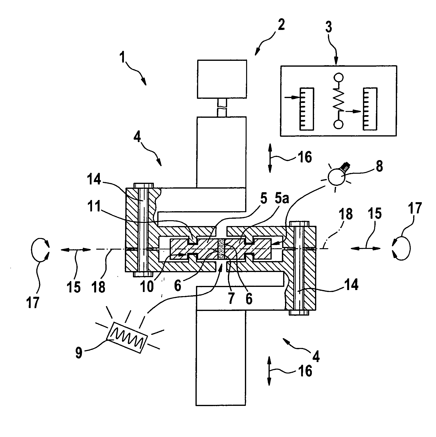
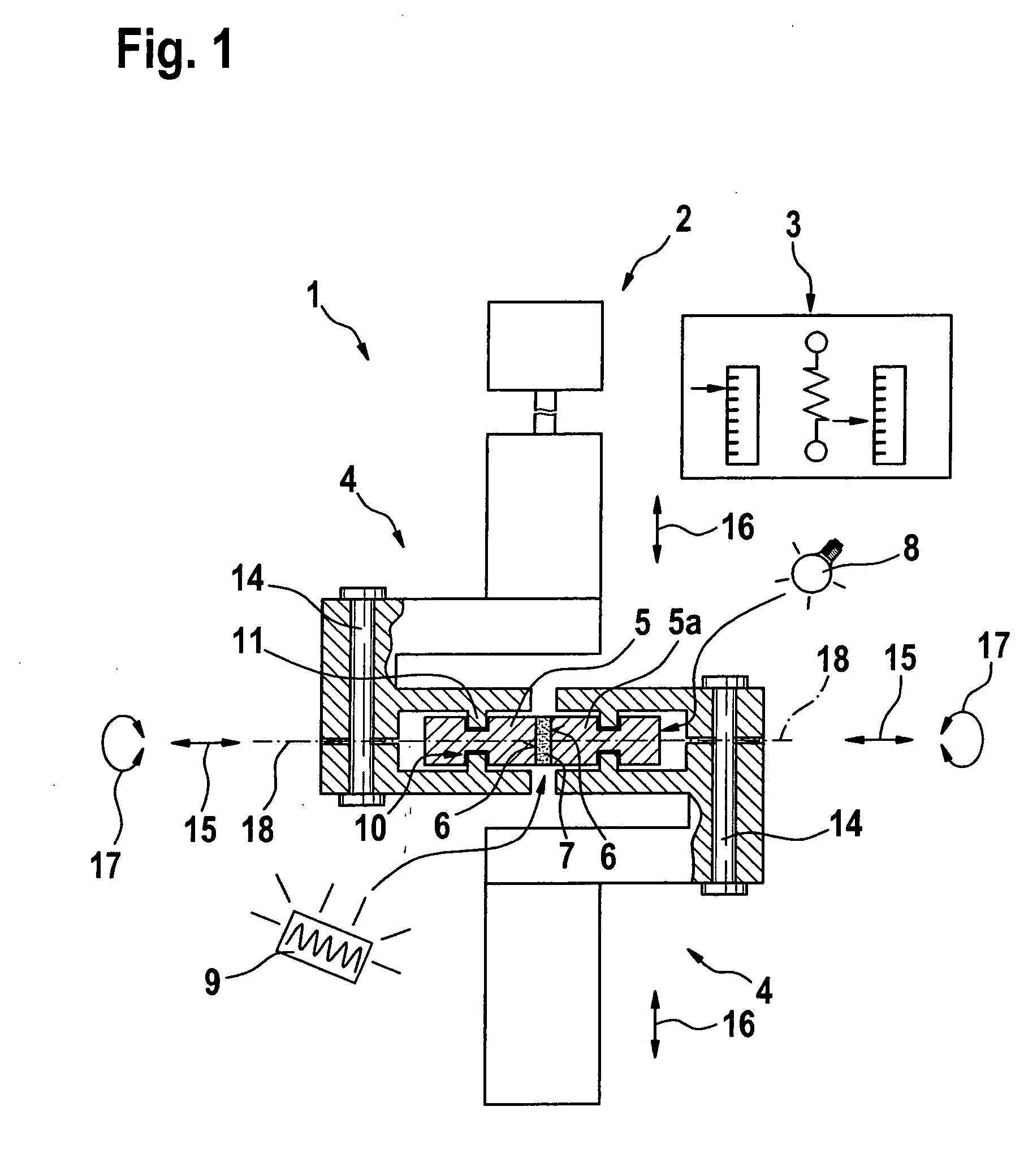
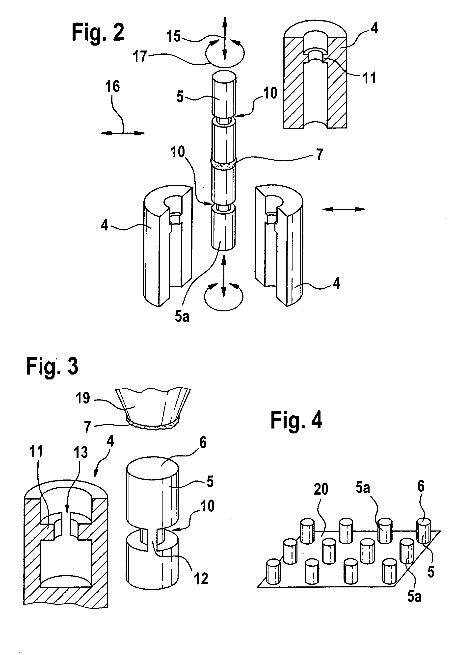
[0026]FIG. 1 shows a device 1 for testing material properties with regard to combined tensile and shear loads, in particular for testing adhesives. This device has a device 2 for applying the force and a measuring device 3. Test pieces 5, 5a are fixed on device 1 via test piece receptacles 4. Bonding surfaces 6 are formed on the front faces of the test pieces and are bonded by adhesive 7 to be tested.

[0027] Test pieces 5, 5a are made of a material permeable to electromagnetic waves, so that the electromagnetic waves exiting from the respective sources are able to act on the adhesive to be tested from each side. A UV light source 8 and, as another example, a heat source 9 are depicted as sources. Depending on the embodiment, the source for heat supply may be situated directly in the area of the joint or at a suitable radiation entry point for the UV light. A properly conducting connection from the respective source to the joint or to the wave entry point may also be present, so that...


PUM


Abstract

A device for testing material properties with regard to combined tensile and shear loads, in particular for testing adhesives, includes a device for applying the force, a measuring device, a test piece receptacle, and a test piece having a bonding surface. The test piece is dimensionally stable within the intended limits of the force to be applied. This measure ensures that the shear forces acting on the joint act approximately at a right angle to the bonding surface over the entire test period, so that realistic conclusions may be drawn with regard to the material properties of the tested adhesive.

Description

BACKGROUND INFORMATION [0001] Different methods and devices are used for characterizing adhesives. The most common test is the combined tensile and shear test. Two standard test strips are bonded together as test pieces and are pulled apart after hardening of the adhesive. The measured force up to the breaking point of the joint is a measure for the adhesive strength. This test is easily performed; however, due to the asymmetrical tensile load, twisting of the joint along the action of the force occurs in the two test strips. The tensile force no longer acts on the bonding surface at a right angle, which makes it impossible to draw an unambiguous conclusion about the adhesive's tensile properties. [0002] A material which is mechanically stronger than the test strips is used in an approach known as the “thick combined tensile and shear test.” For forming a test piece, two oblong strips having a sufficient thickness and width are bonded on top of one another over the entire surface. S...

Claims


Application Information

Patent Timeline
IPC IPC(8): G01N3/24G01N19/04G01R31/26
CPCG01N3/08G01N3/24G01N2203/04G01N2203/0266G01N19/04
Inventor BRINZ, THOMASLEWIS, JANEGEIGER, THOMAS
Owner ROBERT BOSCH GMBH
Why Eureka
Try Eureka