Wearable jacket having communication function, and endoscope system employing wearable jacket

a technology of communication function and wearable jacket, which is applied in the field of wearable antenna jacket, can solve the problems of difficult to insert such an endoscope in a thin, long and meandering portion, and burdensome subject observation using such an endoscop

Inactive Publication Date: 2005-09-08
ASAHI KOGAKU KOGYO KK
View PDF64 Cites 30 Cited by
  • Summary
  • Abstract
  • Description
  • Claims
  • Application Information

AI Technical Summary

Benefits of technology

[0009] The present invention is advantageous in that an improved endoscope system employing a capsule endoscope and overcoming the above problems is provided. That is, according to the improved endoscope system, a wearable jacket is provided.

Problems solved by technology

Therefore, observation using such an endoscope is burdensome to the subject (examinee).
Further, it is difficult to insert such an endoscope in a thin, long and meandering portion, such as intestine.
Such a structure has, however, several deficiencies.
Therefore, for mounting each antenna, a relatively large area is required and it is difficult to mount many antennas on the belt.
However, if the cables (or lead wires) are mounted, the flexibility is lost.
Further, if a large number of cables (lead wires) are mounted, the weight of the belt significantl

Method used


Image

  • Wearable jacket having communication function, and endoscope system employing wearable jacket
  • Wearable jacket having communication function, and endoscope system employing wearable jacket
  • Wearable jacket having communication function, and endoscope system employing wearable jacket

Examples


first embodiment

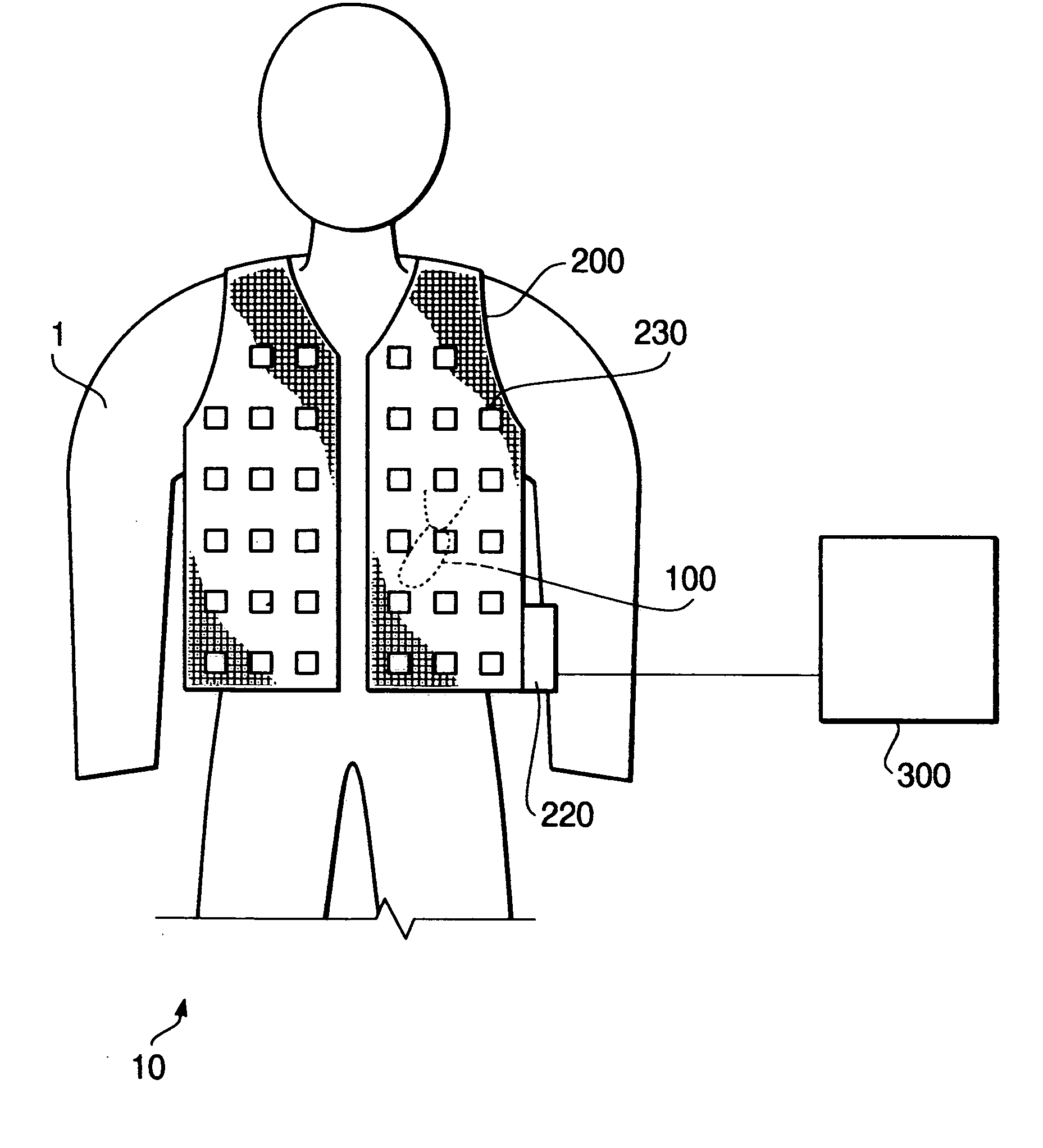
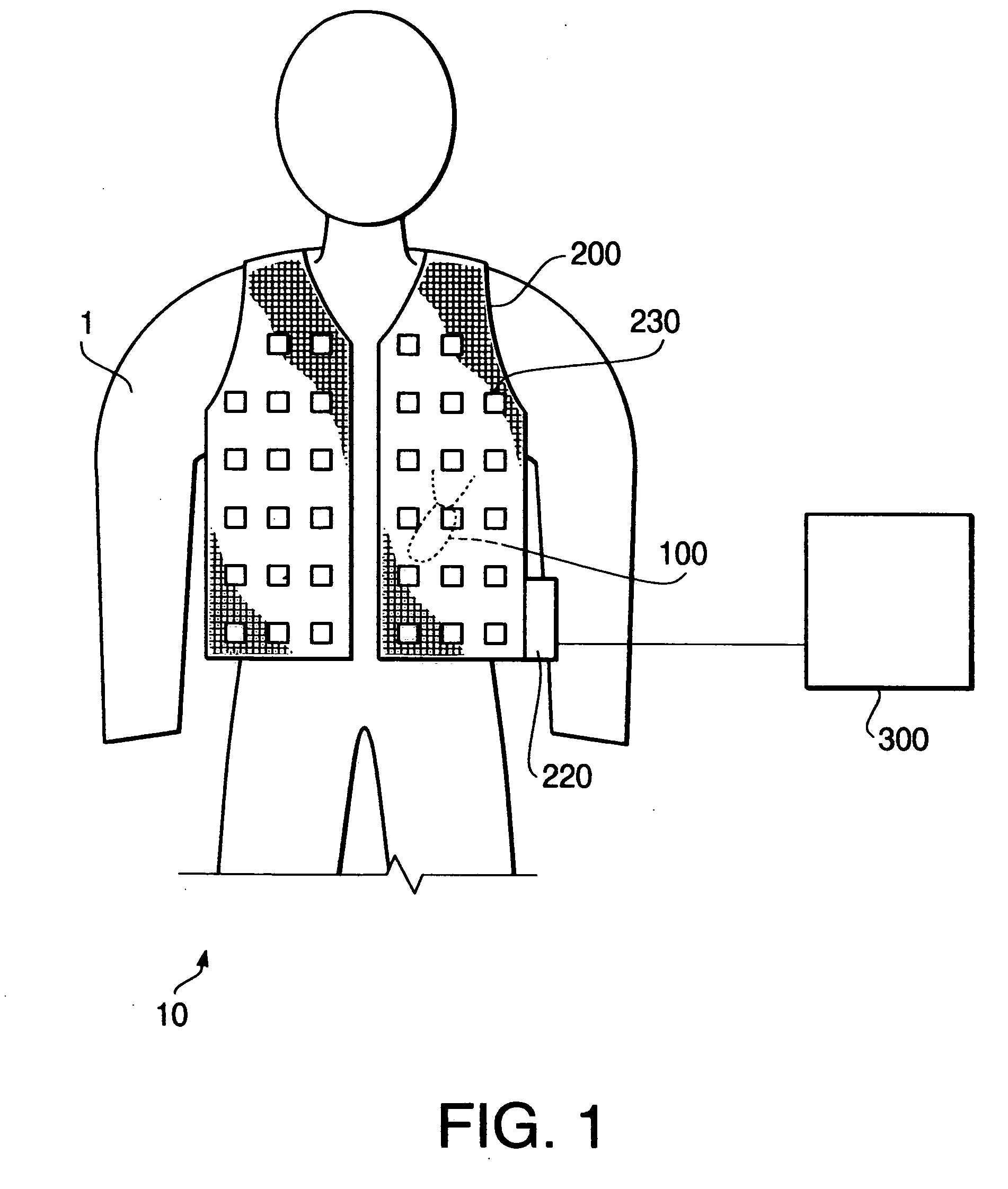
[0044]FIG. 1 schematically shows a configuration of the endoscope system 10 according to an embodiment of the invention. The endoscope system 10 is used, for example, to obtain the body functions (e.g., pulse, blood pressure, temperature etc.) and / or image information of body cavities and the like of the subject 1. Such data is used for diagnosing the subject 1.

[0045] As shown in FIG. 1, the endoscope system 10 includes a capsule endoscope 100 which is inserted (swallowed) inside the subject 1, an antenna jacket 200, and a personal computer (PC) 300. The capsule endoscope 100 captures images inside the subject 1 and outputs image data by radio. The antenna jacket 200 is provided with a plurality of antennas and circuits, and receives the image data output by the capsule endoscope 100. The antenna jacket 200 transmits the obtained signal and data related to the body functions to the PC 300. The PC 300 is provided with a display, which displays the data (e.g., image data) received fr...

second embodiment

[0103]FIG. 11 shows a flowchart illustrating a data obtaining procedure executed by the control unit 220 according to the second embodiment. According to the procedure shown in FIG. 7, the reception module is selected every time the obtained image and the body function data is stored in the memory 224. According to the second embodiment, the reception module is selected at every predetermined timing. In the following description on FIG. 11, the steps which are the same as those in FIG. 7 will be assigned with the same step numbers and description thereof will be omitted for the brevity.

[0104] When the power switch of the control unit 220 is ON and the ID data setting process is executed in S1, controller 221 starts a counter A (which has an initial value of zero) in S31. The counter A is referred to in S33, which will be described later. After controller 221 judges whether the power source is OFF in S2, and steps S3 and S4 are executed, the controller 221 increments the counter A b...

third embodiment

[0110]FIG. 12 is a flowchart of the data obtaining procedure according to a third embodiment. According to the procedure shown in FIG. 12, acquisition of the image data, acquisition of the body function data and selection of the reception module are executed at different timings. It should be noted that the steps same as those in FIG. 7 or FIG. 11 will be assigned with the same step numbers and description thereof will be omitted for the brevity.

[0111] When the power switch (not shown) is turned ON and the ID data setting process is executed in S1, controller 221 starts the counters A (initial value=0) and B (initial value=0) in S31. After judgment in S2, reception module selection procedure in S3 and path determining procedure in S4 are finished, the controller 221 increments the counter A by one (S32).

[0112] When steps S5 and S6 are finished (i.e., the image signal is transmitted to the control unit 220 and stored in the memory 224), the controller 221 judges whether the value o...


PUM


Abstract

A wearable jacket includes a 2D-DST substrate shaped to cover a body of a subject person. The 2D-DST substrate includes a first conductive sheet, a second conductive sheet and a plurality of communication modules. The first and second conductive sheets are overlapped, and the first conductive sheet is located on the subject person side when in use. The plurality of communication modules are distributed between the first and second conductive sheets. At least one of the plurality of communication modules has a communicating system capable of communicating with an external device by receiving and/or transmitting a spatially propagating signal. One of the first and second conductive sheets on the external device side is formed with an area that allows the spatially propagating signal to pass through at a position corresponding to a location of a communication module having the communicating system.

Description

BACKGROUND OF THE INVENTION [0001] The present invention relates to a wearable antenna jacket for use with an endoscope system having a communication function used for obtaining information related to a body of a subject, and an endoscope system employing such a wearable jacket. [0002] Conventionally, when a human body of a subject is observed, an electronic endoscope is typically used. The electronic endoscope is provided with cables and optical fibers inside a flexible tube section of a scope, and at a tip thereof, an imaging element such as a CCD (Charge Coupled Device), is fixed. Such an endoscope is configured such that a relatively long flexible tube is inserted in the human cavity. Therefore, observation using such an endoscope is burdensome to the subject (examinee). Further, it is difficult to insert such an endoscope in a thin, long and meandering portion, such as intestine. [0003] Recently, in order to decrease the burden to the subject, a system employing a capsule type ...

Claims


Application Information

Patent Timeline
IPC IPC(8): A41D1/00A61B5/00A41D1/02A61B1/00A61B1/04A61B1/05A61B5/01A61B5/0205A61B5/021A61B5/024A61B5/026A61B5/04A61B5/0408A61B5/0478A61B5/06A61B5/07A61B5/08A61B5/145G08C17/02H01Q1/12
CPCA61B1/00016A61B1/0002A61B1/00029A61B1/041A61B5/01A61B5/0205A61B2560/0219A61B5/024A61B5/026A61B5/06A61B5/0816A61B5/4261A61B5/6805A61B5/021A61B5/062
Inventor ITO, EIICHIMATSUMOTO, MITSUHIROTSUDA, KOJIHONJO, MASAYUKI
Owner ASAHI KOGAKU KOGYO KK
Why Eureka
Try Eureka