Information entry system

a technology of information entry and information entry, applied in the field of information entry system, can solve the problems of difficult use of type of device, stealing another person, and a lot of time to push, and achieve the effect of easing the pressing of keys

Inactive Publication Date: 2005-09-08
HABU TOMOHIRO
View PDF6 Cites 26 Cited by
  • Summary
  • Abstract
  • Description
  • Claims
  • Application Information

AI Technical Summary

Benefits of technology

[0008] The objective of this invention is to protect the information entry such as a PIN from theft by observation of the movement of our finger based on the fixed a

Problems solved by technology

However, this fixed arrangement makes it easy for another person to steal the PIN we enter by glancing at the movement of our finger based on the fixed arrangement of the keys.
But this type of device is difficult to use, as the order of keys is random.
This random arrange

Method used


Image

  • Information entry system
  • Information entry system
  • Information entry system

Examples


Embodiment Construction

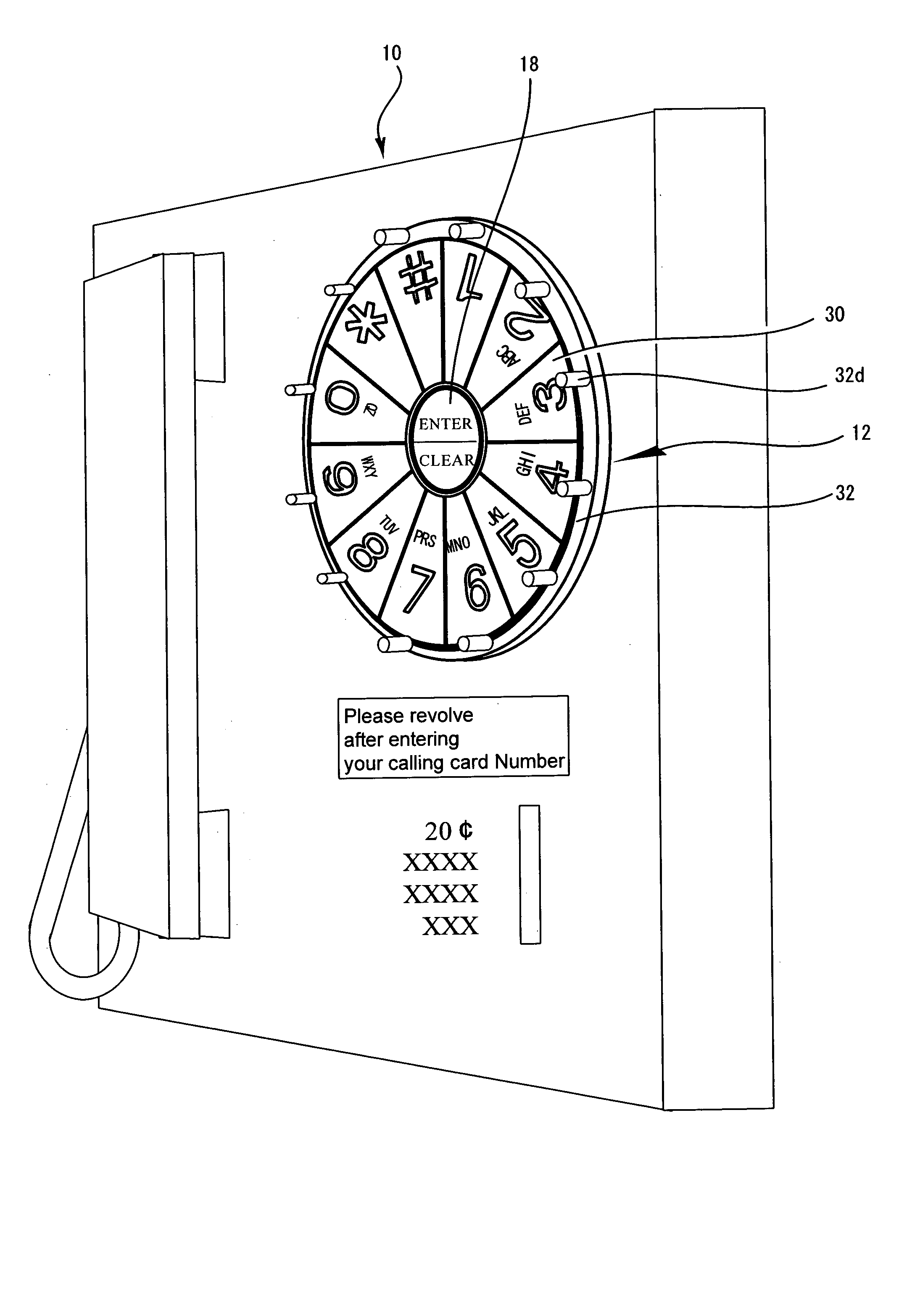
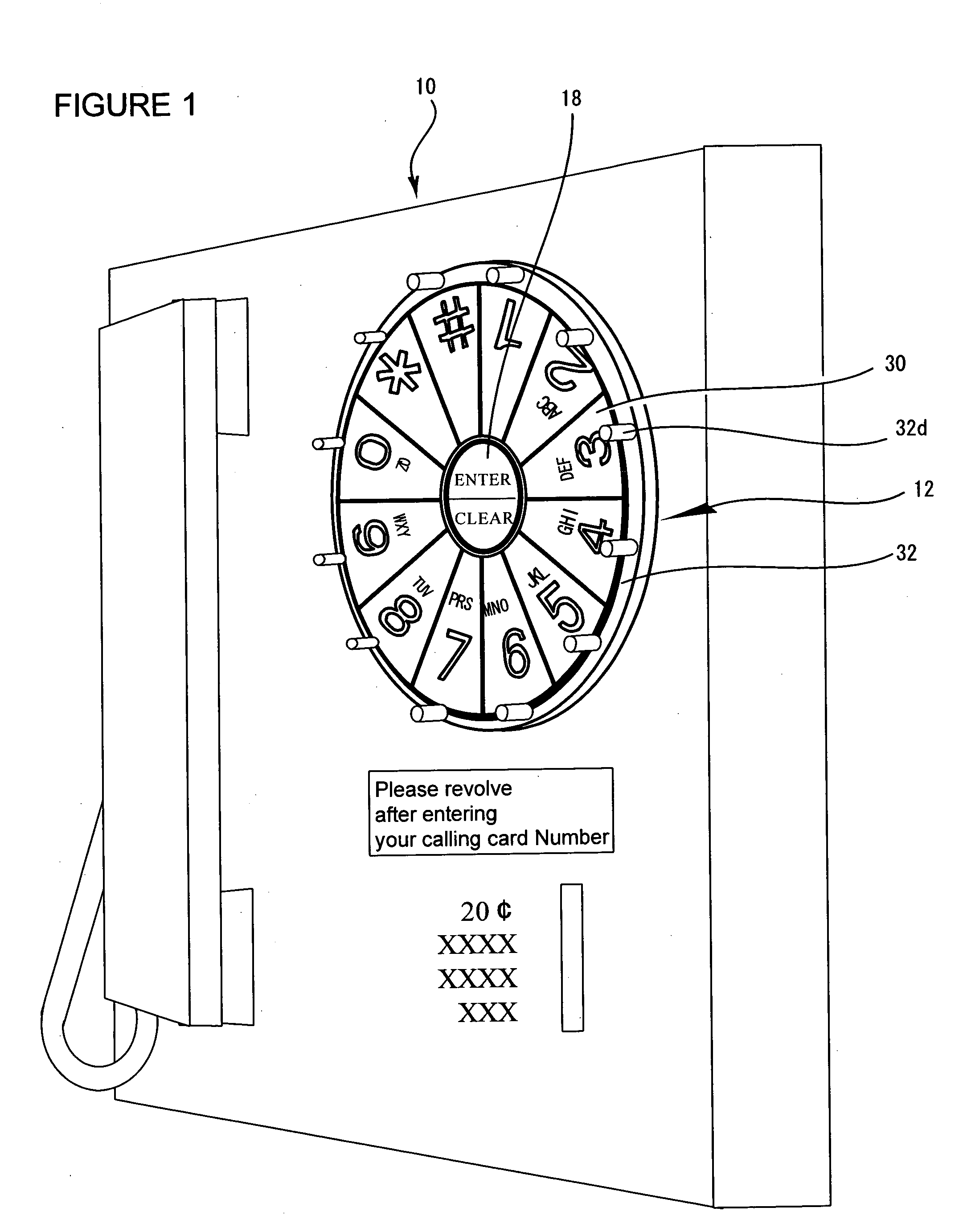
[0023] Although the spirit and scope of the present invention is best described with the main non-mechanical embodiment referring to FIG. 7-10, in order to explain the invention in depth, a mechanical example is described with the mechanical embodiment, referring FIG. 1-6.

[0024]FIG. 1 is the perspective view of a public phone for which this device is adapted. The information entry device of this invention 12 is attached to the body of the public phone 10.

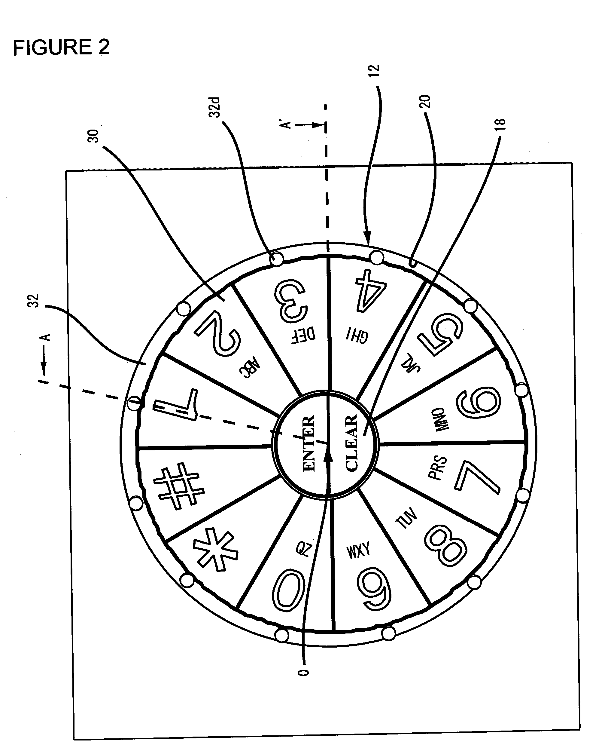
[0025]FIG. 2 is the expanded view from the front of the information entry device 12. In FIG. 3, the cross-sectional view along the line A-O and the cross-sectional view along the line A′-O are shown side-by-side. A center button of “Enter / Clear”18 is installed on the body of the public phone 10 at the center of the information entry device 12. A groove 20 is concentrically provided around the center button 18 as shown in FIGS. 2 and 3. Each key 30 has a button comprising connection elements 34,36, and 38, which send the electronic...


PUM


Abstract

The objective of this invention is to protect the information entry such as a PIN from theft by observation of the finger movement based on the conventional fixed arrangement of entry keys. The present invention is an information entry system comprising a touch panel monitor screen, wherein the touch panel monitor screen displays keys for information entry, which are arranged circularly in order and rotates around the center of the circular arrangement without changing the order when a user touches a predetermined option key. This system also have a central processing unit and a program storage unit including an Information entry Screen Generator, a Random Number Generator, a Key Moving Unit, and an PIN Information output unit. This information entry device prevents a PIN or any other information entry from being stolen by someone who glances at the finger movement, since the entire series of the entry keys are rotated before or after the PIN entry. The information entry system of the present invention can be adapted for an ATM or PDA terminal as well as for a touch panel screen monitor.

Description

CROSS-REFERENCE TO RELATED APPLICATION [0001] This application is a continuation-in-part application, based on U.S. application Ser. No. 09 / 758,335, filed on Jan. 12, 2001, the disclosure of which is incorporated by reference.BACKGROUND OF THE INVENTION [0002] 1. Technical Field of the Invention [0003] This invention relates to an information entry system, wherein provision is made for protecting the information entry such as a PIN from being stolen. [0004] 2. Description of Prior Art / Current Technology [0005] Various kinds of financial transaction services are provided by using IT (Information Technology) these days, such as credit cards, debit cards, digital wallets by use of smart cards and so on. Information of the card is kept in the magnetic stripe or IC chip of the card. Also, we can now use a public phone by entering a call card number instead of inserting a coin. [0006] To use these services, a PIN or password entry is required for user identification. Nowadays using a cred...

Claims


Application Information

Patent Timeline
IPC IPC(8): G06F3/023G06F3/033G06F3/048G06F21/00G07F7/10G07F19/00H04M1/23
CPCG06F3/0219G06F3/0488G06F21/83H04M1/23G07F19/20G07F19/201G07F7/10
Inventor HABU, TOMOHIRO
Owner HABU TOMOHIRO
Why Eureka
Try Eureka