Heat dissipating pin structure for mitigation of LED temperature rise

a heat dissipation pin and temperature rise technology, applied in the direction of electrical equipment construction details, lighting and heating apparatus, transportation and packaging, etc., can solve the problems of heat rising, led being permanently damaged, and presenting a phenomenon of temperature rise, so as to improve the heat dissipation capability of densely arranged and improve the quality of led.

Active Publication Date: 2005-09-08
SHANGHAI SANSI TECH
View PDF8 Cites 6 Cited by
  • Summary
  • Abstract
  • Description
  • Claims
  • Application Information

AI Technical Summary

Benefits of technology

[0004] The present invention aims to overcome the shortcoming of having difficulty in heat dissipating when LEDs are densely arranged, and to provide a heat-dissipating pin structure for mitigation of LED temperature rise, thereby effectively enhancing the heat dissipating capability of densely arranged LED chips or PCB's of light-emitting diodes, providing more suitable working environmental temperature for LED, insuring better displaying quality of LED, and guaranteeing normal working life of LED.
[0010] In the present invention, based on principle of heat conduction, heat generated in LEDs propagates and dissipates along metallic foil circuit or foil surface and by means of above said pins, wherein heat conducts rapidly due to increase in cross-sectional area and radiates rapidly to surrounding atmosphere due to increase in surface area of heat-dissipating pins, thereby effectively achieving rapid dissipation of heat, suppressing temperature rise of LED working environment, ensuring displaying quality of LED, and guaranteeing normal working life of LED.

Problems solved by technology

Energized LED (light-emitting diode) will present a phenomenon of temperature rise, which is especially serious in case of large LED chip or when LED's are densely arranged.
In that event LED lightness is impaired, radiation wavelength of LED be changed, working life of LED is influenced, and even LED will be permanently damaged.
Along with continuous extension of LED application, more and more super-bright full-color large LED display screens and LED illuminating devices, where LED's are densely arranged, are widely applied and have brought forth problem of heat rising.
But these measures are limited by such highly dense arrangement of circuits on PCB, so that heat dissipation effects are seriously restricted, and up to now there is no ideal heat dissipation structure for PCB of LED's.

Method used


Image

  • Heat dissipating pin structure for mitigation of LED temperature rise
  • Heat dissipating pin structure for mitigation of LED temperature rise
  • Heat dissipating pin structure for mitigation of LED temperature rise

Examples


embodiment 1

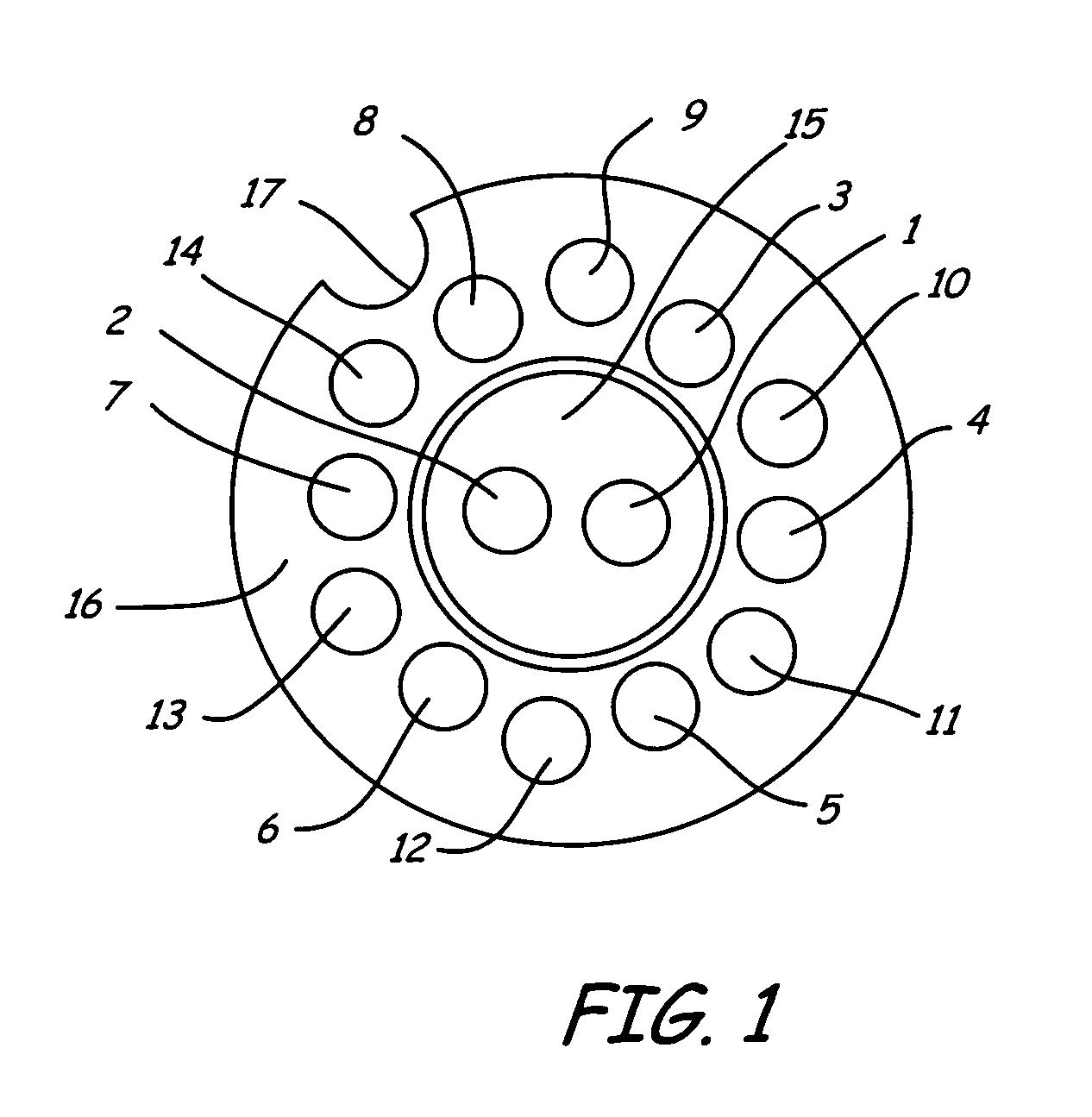
[0017]FIG. 1 shows layout view of a PCB of LED light of 5 mm in diameter with 6 LED chips, in which 6 LED chips being in parallel connection Metallic pins of Φ 0.46×10.24 mm are led out through holes 1-8 respectively, wherein holes 1-2 are used for two pinouts of same polarity of LED, and holes 3-8 are used for 6 pinouts of another polarity of LED. Holes 9-14 are used as running holes for encapsulation of epoxy resin and no metallic pins are led out from there. Reference numerals 15 and 16 denote copper foil surfaces of PCB, on which metallic pins are riveted perpendicularly. Numeral 17 is a gap for positioning. In this embodiment, above said 8 heat-dissipating pins also serve for electric pinouts, and 6 LED chips are directly secured on top ends of No. 3-8 heat-dissipating pins by means of brazing technique, so that top end of each LED chip is electrically connected to copper foil surface 15, wherein pin 1-2 serve for electric pinouts. Heat generated after energizing of said LED is...

embodiment 2

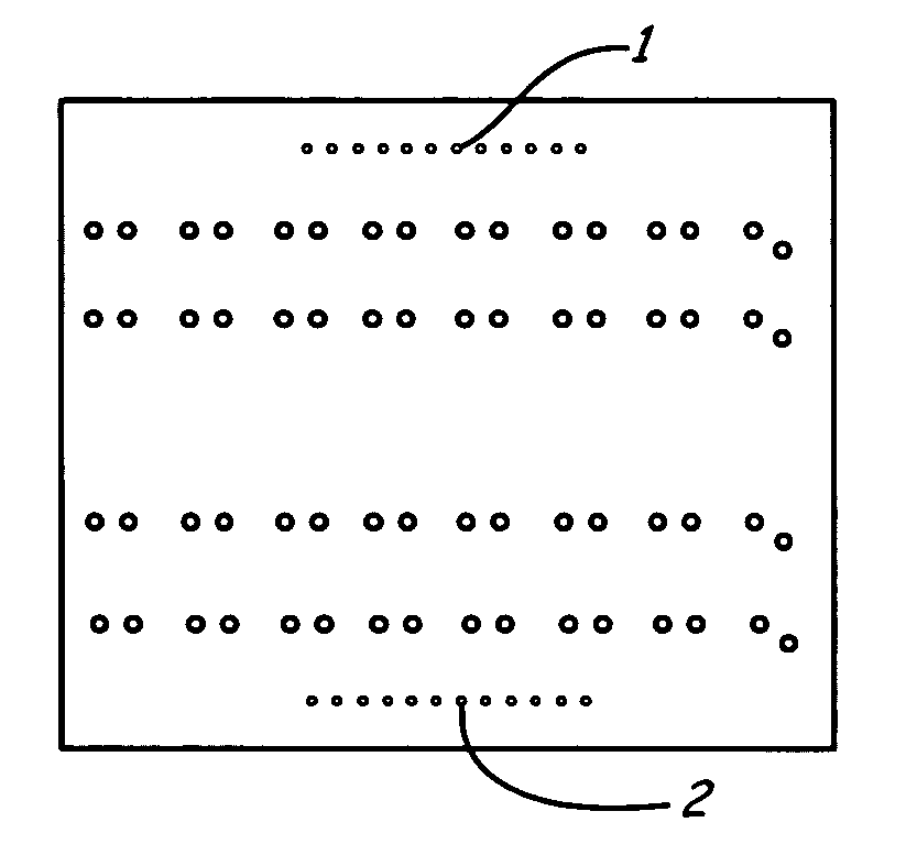
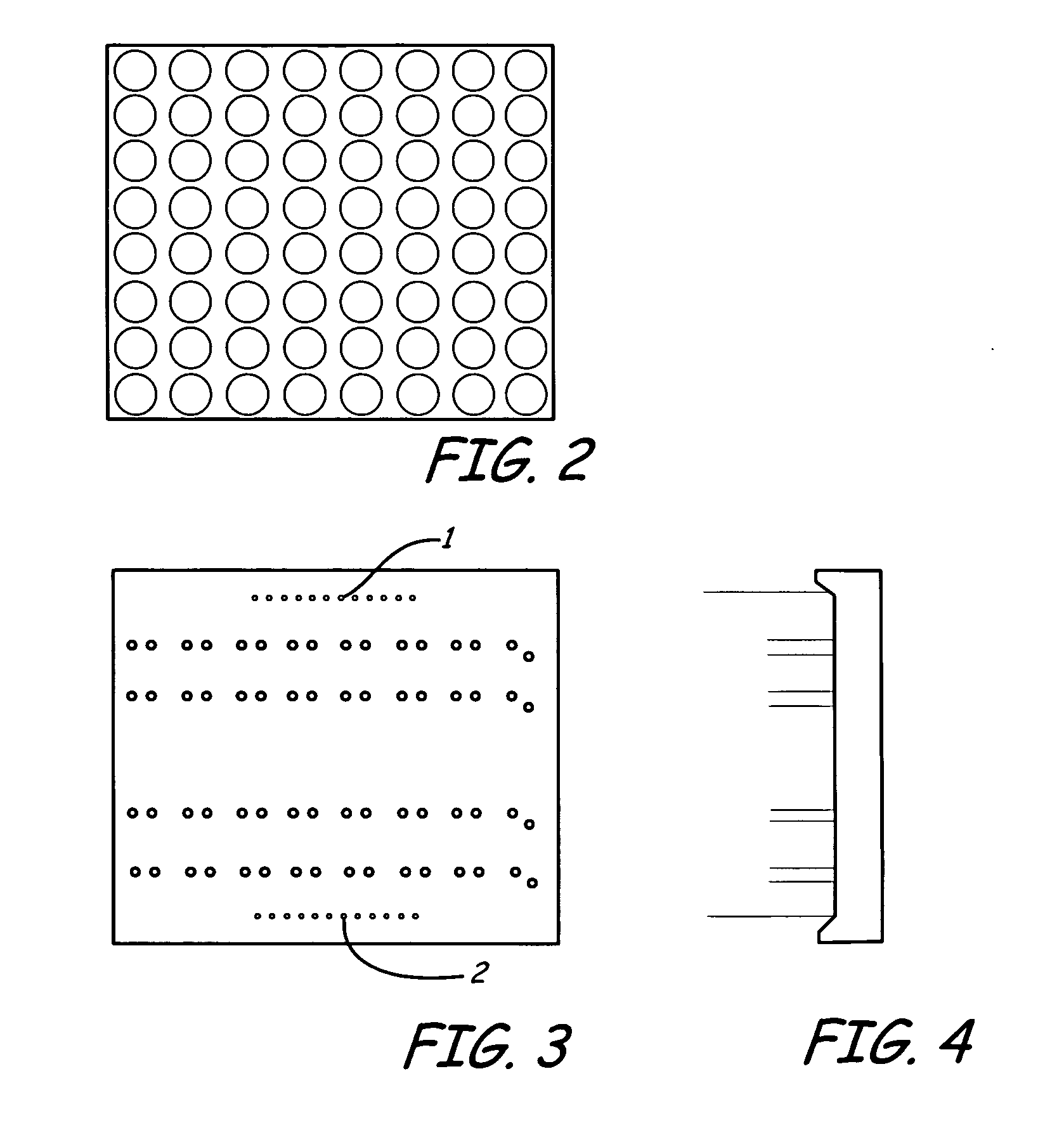
[0018]FIG. 2 shows front view of a bi-color LED matrix display module with 8×8 pixels of 10 mm spacing (face of reflection chamber set). FIGS. 3 and 4 show back view (PCB back face) and side view of FIG. 2 respectively, wherein reference numeral 1 and 2 in FIG. 3 denote two rows of pinouts (12 in each tow), and in remaining 4 rows 16 heat-dissipating pins are arranged in each row, wherein the rightmost pin is staggered in position due to limitation in arrangement of PCB. According to the circuit layout and the need of heat-dissipation, heat-dissipating pins of same column in present embodiment are connected in same polarity in electric circuit, but heat-dissipating pins of different columns should not be in contact to avoid short circuit.

[0019] It can be seen from FIG. 4 that all heat-dissipating pins are shorter than electric pinouts. When electric pinouts of displaying module are brazed on corresponding driving PCB, all heat-dissipating pins are exposed outside and not in contact...


PUM


Abstract

A heat-dissipating pin structure for mitigation of LED temperature rise, characterized in that: on metallic foil circuit or foil surfaced of PCB connecting to joining surface of LED chip, on which LED chips or light-emitting diodes of surface-mounting type or light-emitting single tube will be installed, are provided a plurality of small perpendicular through holes, in which are inserted loose-fitted and heat-conductive pins, and ends of these pins are adapted to be riveted perpendicularly or brazed directly to PCB, so that pins inserted in these holes can be fixed vertically on the back surface of PCB. Based on the principle of heat conduction, in the present invention heat generated in LED's propagates and dissipates along metallic circuit or foil surface and by means of above said pins, wherein heat conducts rapidly due to increase in cross-sectional area and radiates rapidly to surrounding atmosphere due to increase in surface area of heat-dissipating pins, thereby effectively achieving rapid dissipation of heat, suppressing temperature rise of LED working environment, ensuring displaying quality of LED, and guaranteeing normal working life of LED.

Description

FIELD OF THE INVENTION [0001] This invention relates to application of LED (light-emitting diode), and particularly to heat dissipation technique in LED application. BACKGROUND OF INVENTION [0002] Energized LED (light-emitting diode) will present a phenomenon of temperature rise, which is especially serious in case of large LED chip or when LED's are densely arranged. In that event LED lightness is impaired, radiation wavelength of LED be changed, working life of LED is influenced, and even LED will be permanently damaged. [0003] Along with continuous extension of LED application, more and more super-bright full-color large LED display screens and LED illuminating devices, where LED's are densely arranged, are widely applied and have brought forth problem of heat rising. It is important for LED to achieve good heat dissipation. Conventional methods of heat dissipation for LED are embodied in forming technology of LED, e.g. metallic pinouts of LED are made of flat metal strips. Usual...

Claims


Application Information

Patent Timeline
Patent Type & Authority Applications(United States)
IPC IPC(8): H01L23/34H05K7/20
CPCH01L23/3677H01L33/642H05K1/0203H05K3/306H01L2924/0002H05K2201/10106H01L2924/00
Inventor CHEN, BISHOULI, SHENGLI, LEKE
Owner SHANGHAI SANSI TECH
Why Eureka
Try Eureka