Image input apparatus and inspection apparatus

Inactive Publication Date: 2005-09-08
KK TOSHIBA +1
View PDF3 Cites 45 Cited by
  • Summary
  • Abstract
  • Description
  • Claims
  • Application Information

AI Technical Summary

Benefits of technology

[0010] An object of the present invention is to precisely input an

Problems solved by technology

In this apparatus, because an image fetching speed of the area type CCD camera 202 is slow, there are the problems a rate of the inspection speed is limited, and it is necessary to correct a change in a quantity of laser light generated during the time of fetching an image by the CCD camera.
In this case, when a change in the speed of the stage 213 is brought about, there is the problem that the resolution of an image obtained by the TDI sensor 212 deter

Method used


Image

  • Image input apparatus and inspection apparatus
  • Image input apparatus and inspection apparatus
  • Image input apparatus and inspection apparatus

Examples


first embodiment

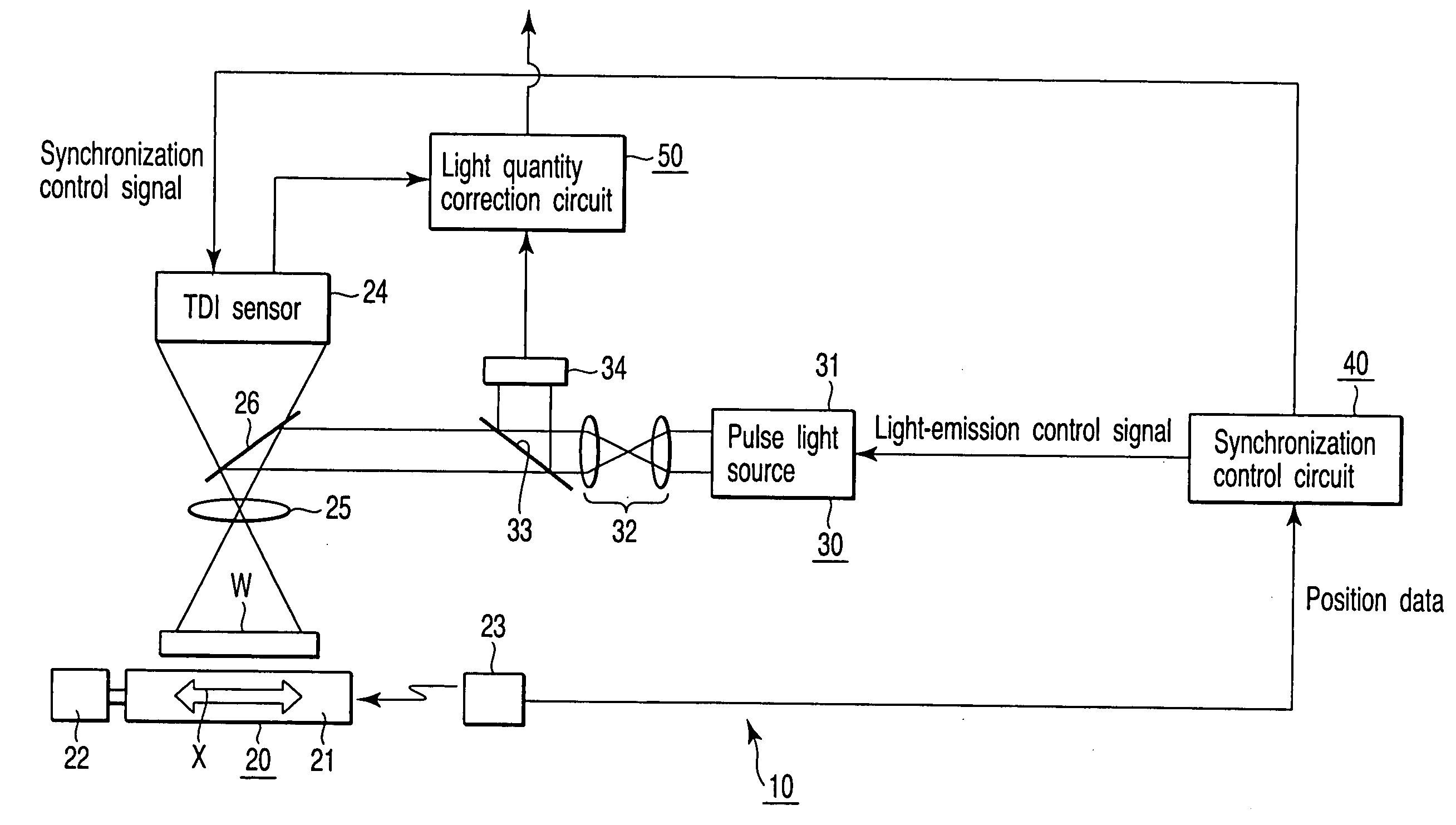
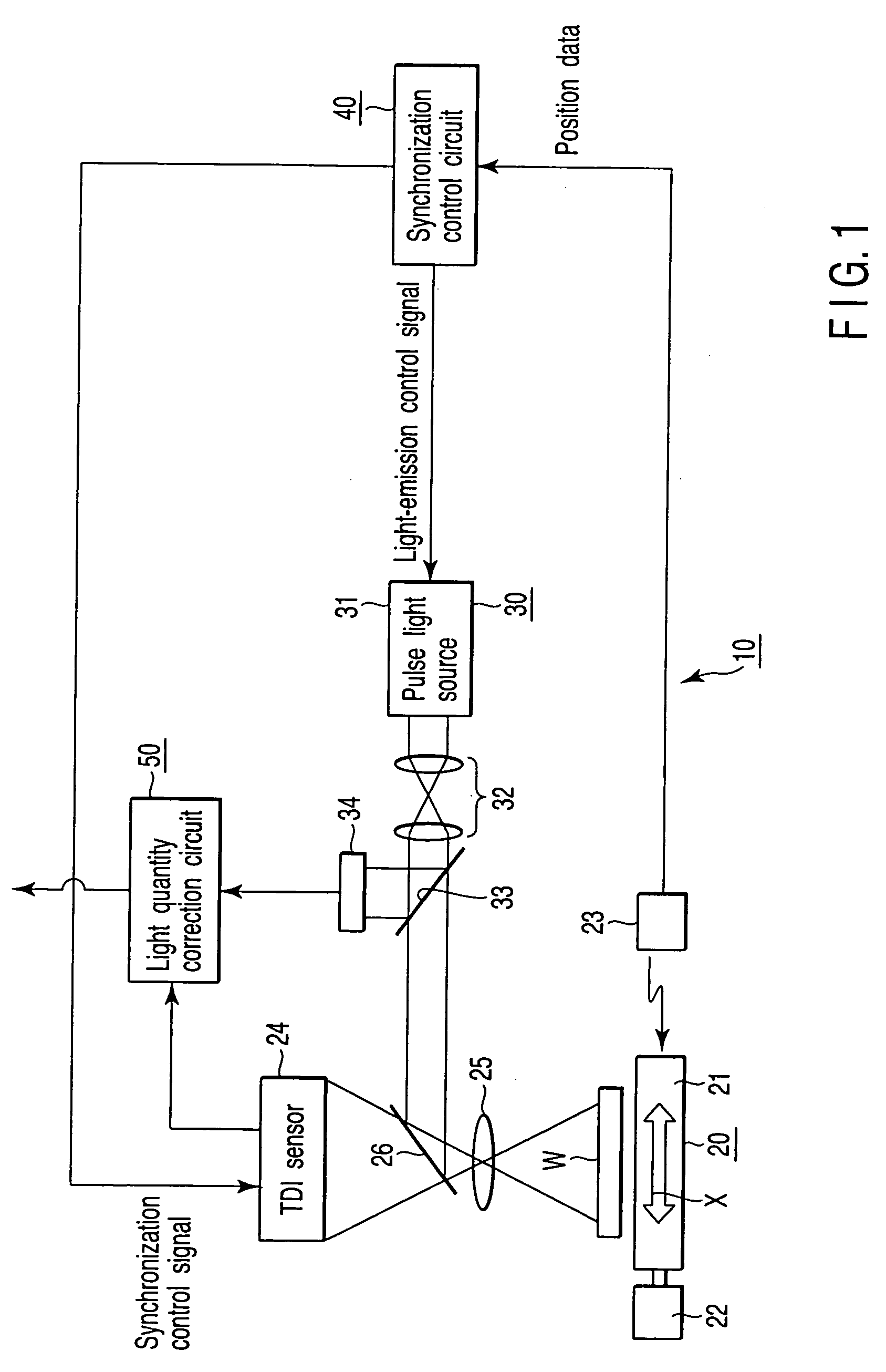
[0031]FIG. 1 is an explanatory diagram showing a configuration of an image input apparatus 10 according to the present invention. The image input apparatus 10 has an image input section 20, an illumination section 30, a synchronization control circuit 40, and a light quantity correction circuit 50. The image input section 20 outputs a magnified optical image of an object as an electric image signal. The illumination section 30 illuminates an object. The synchronization control circuit 40 generates a synchronization control signal (a scan clock) of a TDI sensor 24 on the basis of position data of a laser interferometer 23, and controls a light-emission interval of a pulse light source 31. The light quantity correction circuit 50 offsets a change in a level of a quantity of light.

[0032] The image input section 20 has a stage 21 for supporting a wafer W serving as an object, a driving mechanism 22 for moving the stage 21 in the direction of the arrow X in FIG. 1, the laser interferomet...

second embodiment

[0057]FIG. 10 is an explanatory diagram showing a configuration of a mask inspection apparatus 60 for an EUV mask according to the present invention. The mask inspection apparatus 60 has an image input section 70, an illumination section 80, a synchronization control circuit 90, a light quantity correction circuit 100, and a defect determination processing section 110. The image input section 70 outputs a magnified optical image of an object as an electric image signal. The illumination section 80 illuminates an object. The synchronization control circuit 90 generates a synchronization control signal of the TDI sensor 24 on the basis of position data of the laser interferometer 73, and controls a light-emission interval of an LPP light source 83. The light quantity correction circuit 100 offsets a change in a level of a light quantity. The defect determination processing section 110 determines the presence / absence of a defect in an EUV mask on the basis of the determined electric im...


PUM


Abstract

An image input apparatus for inputting an image of an object and outputting the image as an electric signal, the image input apparatus comprises a stage which supports the object, a laser interferometer which measures a position of the stage, a light source which emits a pulse light, an illumination optical system which irradiates the object with an illuminating light, a sensor which converts an image-formed optical image into an electric image signal, an imaging optical system which forms an image of the object on the sensor, a synchronization control circuit which controls a light-emission interval of the light source and synchronization of the sensor on the basis of position information of the laser interferometer, a light quantity monitor which measures a quantity of light, and a light quantity correction circuit which corrects the electric image signal on the basis of an output of the light quantity monitor.

Description

CROSS-REFERENCE TO RELATED APPLICATIONS [0001] This application is based upon and claims the benefit of priority from prior Japanese Patent Application No. 2004-048117, filed Feb. 24, 2004, the entire contents of which are incorporated herein by reference. BACKGROUND OF THE INVENTION [0002] 1. Field of the Invention [0003] The present invention relates to an image input apparatus for picking up an image of an object, and an inspection apparatus for inspecting an object by using the image input apparatus, and in particular, to an apparatus for precisely picking up an image of the object, and an apparatus for precisely inspecting and measuring the object, with respect to an object having a fine pattern formed thereon. [0004] 2. Description of the Related Art [0005] In an inspection apparatus for pattern of a photomask, a wafer, or the like, it is necessary to inspect with the resolution of the optical system being improved by using an ultraviolet light source and an optical system in ...

Claims


Application Information

Patent Timeline
IPC IPC(8): G01N21/956G01B11/24G06K9/36G06T1/00H01L21/66
CPCG01N21/9501G03F7/70616G01N2021/95676G01N21/956G01D5/305G01R31/2635G01N21/95684G03F7/70166G01N2021/5957H04N25/768
Inventor INOUE, HIROMUTERASAWA, TSUNEOIMAI, SHINICHINOMURA, TAKEHIKO
Owner KK TOSHIBA
Why Eureka
Try Eureka