
Roller bearing

a roller bearing and roller end technology, applied in the direction of bearings, shafts and bearings, rotary machine parts, etc., can solve the problems of increasing the number of assembling steps, increasing the cost and environmental problems, and the frictional wear of the roller end face tends to be prominent, so as to facilitate the insertion of the roller, increase the assemblability, and maintain the effect of sufficient strength

Active Publication Date: 2005-09-08
NTN CORP
View PDF7 Cites 5 Cited by
  • Summary
  • Abstract
  • Description
  • Claims
  • Application Information

AI Technical Summary

Benefits of technology

[0018] Accordingly, the present invention has devised to substantially eliminate the various problems and inconveniences inherent in the prior art roller bearings and is intended to provide an improved roller bearing assembly of a type utilizing the inner race, which can be assembled with a minimized number of assembling steps and without any drop-off preventing sleeve being employed and which can provide a large load bearing capacity.

Problems solved by technology

Accordingly, with the full complement roller bearing of the type shown in FIG. 11, not only is the number of assembling steps increased, but also increase of the cost and the environment-related problem tend to occur because of the use of the sleeves 31 and 32.
Since the opposite ends of each roller are axially outwardly steepled, the frictional wear of the roller end faces tends to be prominent when the full complement roller bearing of the specific structure is employed in the environment where an induced thrust force is large.
Since the opposite ends of each roller must be processed in any way to have the steeples, the respective roller is costly as compared with the roller having opposite flat end faces.
On the other hand, the full complement roller bearing of the structure, in which the thermally curable grease is filled to constrain the rollers in a non-detachable fashion, has the following problems: The use of the thermally curable grease limits the temperature under which the full type roller bearing of the specific structure can be used and operated.
Means for lubricating the bearing that can be employed, for example, the type of the grease used and the type of oil used, are limited.
In addition, when the roller bearing of a type having a raceway (either an outer race or an inner race) is compared with the raceway-less full complement roller bearing, i.e., the full complement roller bearing having no raceway, of the same sectional height, a problem has been found in that the roller bearing of the type having the raceway tends to have a reduced load bearing capacity.

Method used


Image

  • Roller bearing
  • Roller bearing
  • Roller bearing

Examples


second embodiment

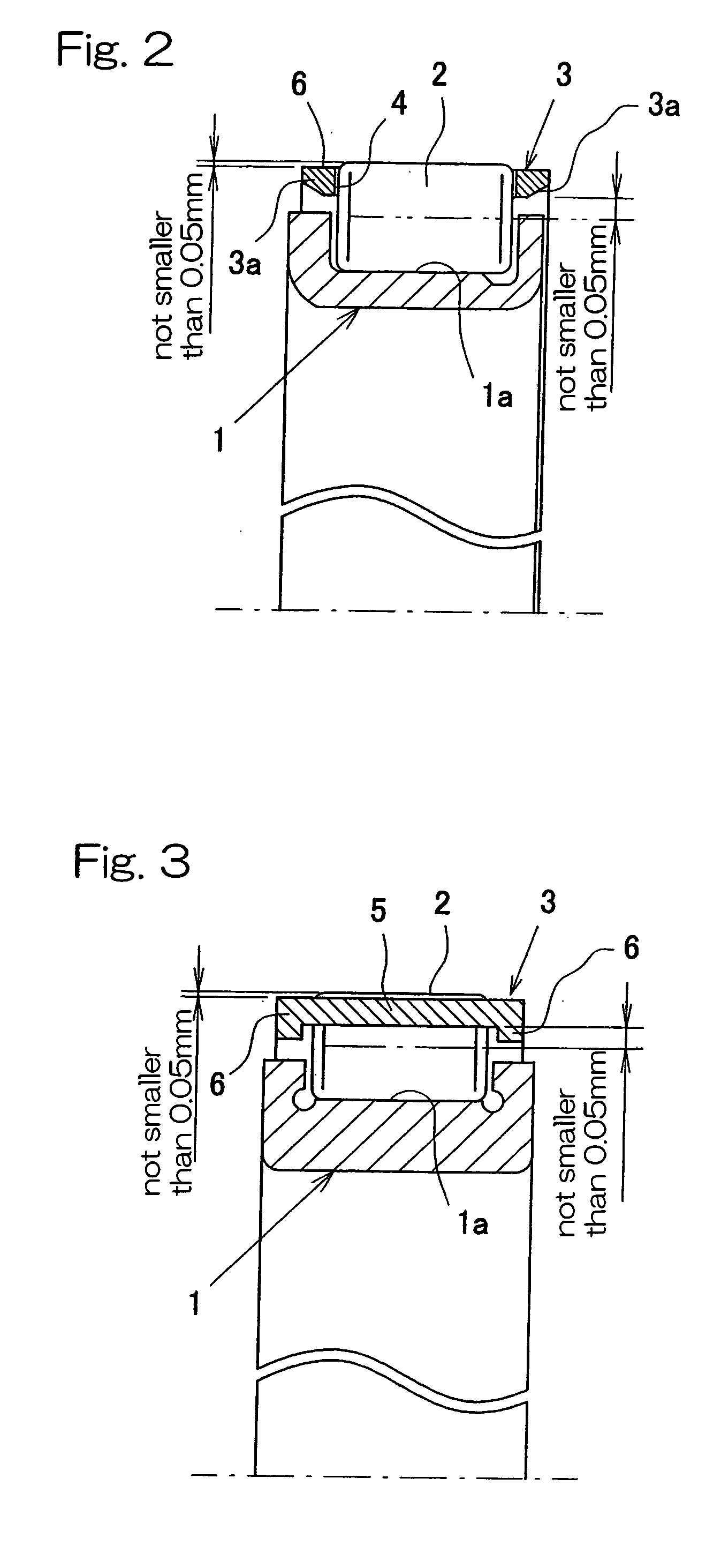
[0077]FIG. 2 illustrates the roller retainer 3 according to a second preferred embodiment of the present invention. In this second embodiment, the inner race 1 is of a drawn cup type, i.e., a press-worked product made of a steel plate. In addition, the roller retainer 3 has opposite end portions 3a of the inner peripheral surface thereof so shaped as to be inclined axially outwardly and upwardly.

[0078] Other structural features of the roller retainer 1 shown in FIG. 2 than those described above are substantially similar to those shown in and described in connection with the previous embodiment with reference to FIGS. 1A and 1B and, therefore, the details thereof are not reiterated for the sake of brevity.

[0079] According to the second embodiment shown in FIG. 2, by allowing the opposite end portions 3a of the inner peripheral surface of the roller retainer 3 to incline axially outwardly and upwardly, the roller retainer 3 can conveniently smoothly be inserted into the outside of th...

third embodiment

[0080]FIG. 3 illustrates the roller retainer 3 according to a third preferred embodiment of the present invention. According to this third embodiment, the inner race 1 is in the form of a machined product formed by machining a steel plate, and the roller retainer 3 is so shaped as to have its axially opposite ring parts 6 each having a thickness, as measured in a direction radially of the roller retainer 3, that is greater than that of each of the pillars 5. Other structural features of the roller retainer 1 shown in FIG. 3 than those described above are substantially similar to those shown in and described in connection with the previous embodiment with reference to FIGS. 1A and 1B and, therefore, the details thereof are not reiterated for the sake of brevity.

first embodiment

[0081] Even with this design, functions and effects similar to those afforded by the first embodiment shown in and described with reference to FIGS. 1A and 1B can be obtained.

[0082]FIGS. 4A to 4D and FIGS. 5A to 5C illustrates a fourth preferred embodiment of the present invention. Any of various forms of the roller retainer 3 according this fourth embodiment is particularly applicable to any one of the first to third embodiments of the present invention shown in and described with reference to FIGS. 1A and 1B, FIG. 2 and FIG. 3, respectively. As shown in FIGS. 4A to 4D, the roller retainer 3 employed in the roller bearing assembly according to any one of the first to third embodiments is formed with a plurality of axial slits 7, 7A at respective locations in a direction circumferentially thereof so as to extend from one end to a position adjacent the opposite end thereof. Except for the use of the axial slits 7, 7A, the roller retainer 3 is of the structure substantially identical ...


PUM


Abstract

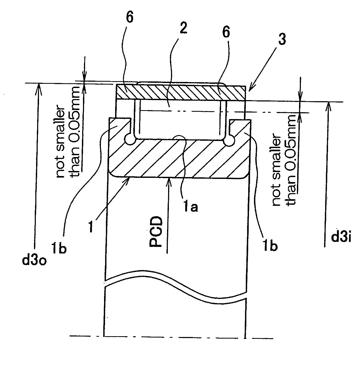
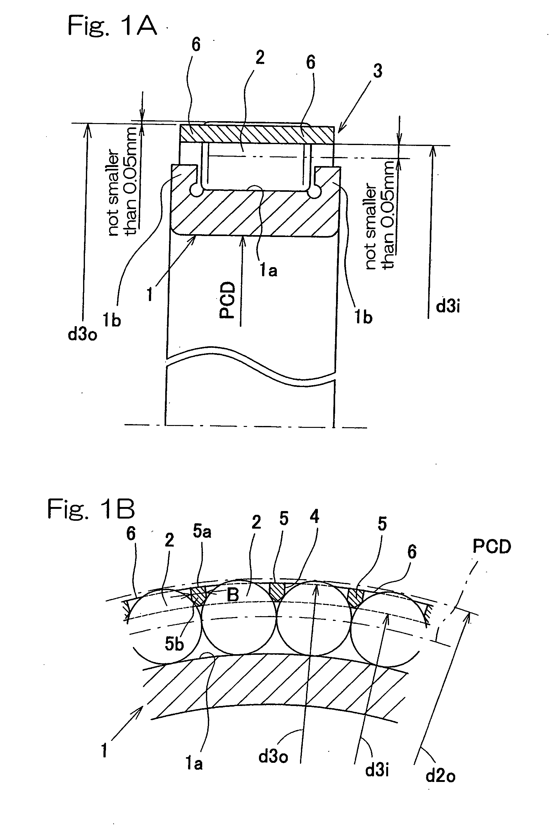
To provide a roller bearing assembly, which can be assembled with a minimized number of assembling steps and without any drop-off preventing sleeve being employed and which can provide a large load bearing capacity, the roller bearing assembly includes an inner race 1 having a raceway surface 1a defined therein, a plurality of rollers 2, and a ring-shaped roller retainer 3 having a plurality of pockets 4 defined therein in a direction circumferentially thereof for accommodating therein the respective rollers 2 in a circular row. The roller retainer 3 also has pillars 5 each defined between the neighboring pockets 4. The roller retainer 3 is positioned on the inner race 1 with each of the pillars 5 thereof intervening between the neighboring rollers 2 to thereby retain the rollers 2 in position within the respective pockets 4 from a direction radially outwardly of the row of the rollers 2. The diameter of the circle depicted by and in touch with the pillars 5 is chosen to be greater than the diameter of the pitch circle PCD depicted in the circular row of the rollers 2.

Description

BACKGROUND OF THE INVENTION [0001] 1. (Field of the Invention) [0002] The present invention generally relates to a roller bearing and, more particularly, to a roller bearing such as, for example, a roller bearing having an inner race and needle roller bearing having a roller retainer, of a kind used in the field of application similar to that of the full complement roller bearing, for example, in a seat reclining mechanism, motorcycle rear suspension link, roller rocker arm and planetary reduction gear unit. [0003] 2. (Description of the Prior Art) [0004] The full complement roller bearing is generally used in the field of application in which the roller bearing is required to have a large load bearing capacity for a limited outer diameter of the roller bearing. Since the full complement roller bearing makes no use of any roller retainer having retainer pillar intervening between the neighboring rollers, both of the number of the rollers used and the load bearing capacity can be inc...

Claims


Application Information

Patent Timeline
Patent Type & Authority Applications(United States)
IPC IPC(8): F16C33/46F16C33/48F16C33/56F16C43/06F16C43/08
CPCF16C33/46F16C2240/84F16C43/08F16C33/4635F16C19/26
Inventor KONO, SHINGOOBAYASHI, KOUSUKEAKAMATSU, HIDEKI
Owner NTN CORP
Learn More