Power tool

a power tool and power technology, applied in the field of power tools, can solve the problems of increasing manufacturing costs and increasing the demand for low noise of power tools, and achieve the effect of sufficient air volume and low nois

Inactive Publication Date: 2005-09-08
HITACHI KOKI CO LTD
View PDF1 Cites 39 Cited by
  • Summary
  • Abstract
  • Description
  • Claims
  • Application Information

AI Technical Summary

Benefits of technology

[0025] Since the first predetermined angle α1 is in a range of 35°≦α1≦45°, and the second predetermined angle α2 is in a range of 2.5°≦α2≦7.5°, it is possible to realize lower noise while maintaining a more sufficient air volume.

Problems solved by technology

However, the demand for the low noise of power tools is becoming increasingly high, and there is a need to optimize the configuration of the centrifugal fan and make the noise smaller.
Since processing becomes difficult such as due to the fact that an end mill is made liable to run out during the formation of the slots, a problem arises in that the manufacturing cost becomes substantially high.

Method used


Image

  • Power tool
  • Power tool
  • Power tool

Examples


Embodiment Construction

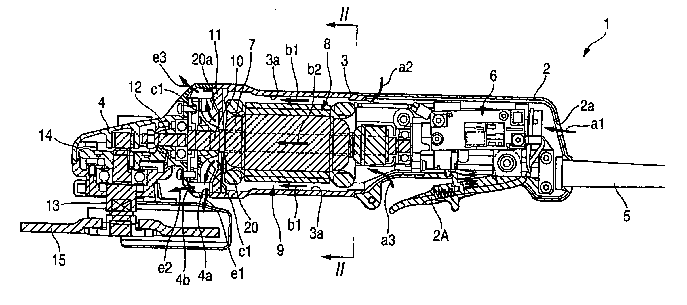
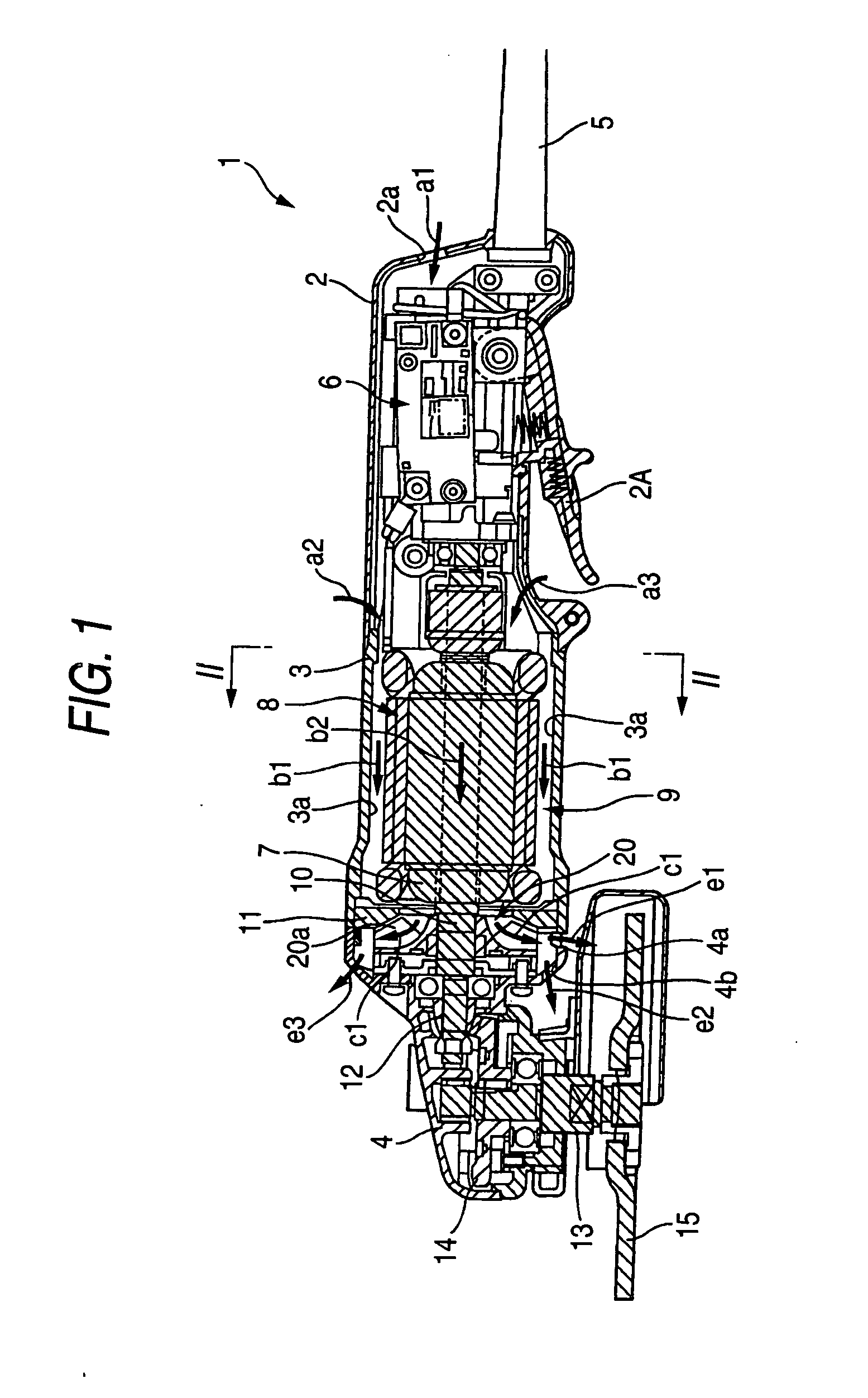
[0037] Referring to FIG. 1, a description will be given of a power tool according to one embodiment of the invention is applied to a grinder (disc grinder).

[0038]FIG. 1 shows an overall structure of a disc grinder 1. If it is assumed that the left-hand side in the drawing is a front end, a resin-made handle portion 2, a resin-made motor housing 3, an aluminum alloy-made gear cover 4 are consecutively connected in that order from the rear side, thereby constituting a housing. Spaces defined in the respective interiors of the handle portion 2, the motor housing 3, and the gear housing 4 communicate with each other. A power supply cable 5 is attached to the handle portion 2, and a switch mechanism 6 is incorporated therein. The switch mechanism 6 is provided with a lever 2A which can be operated by a user. The power supply cable 5 connects the switch mechanism 6 to an external power source (not shown), and the connection and disconnection between the switch mechanism 6 and the power s...


PUM


Abstract

Blades are provided on a fan body such that an outer diameter d2 of the fan body is in a range of 45 mm≦d2≦50 mm, an axial height h1 at a substantially intermediate position of the blade is in a range of 0.2≦h1/d2≦0.3 with respect to the outer diameter of the fan body, and an axial height h2 at an outer peripheral edge of the blade is in a range of 0.12≦h2/d2≦0.17 with respect to the outer diameter d2 of the fan body.

Description

BACKGROUND OF THE INVENTION [0001] 1. Field of the Invention [0002] The present invention relates to a power tool having a centrifugal fan for cooling a motor. [0003] 2. Description of the Related Art [0004] Because of demand for compact size, high output, and low noise of power tools, there has been an increasing need for development of motor cooling fans which are compact and have a high cooling capacity and low noise as well as peripheral components of the fan. Accordingly, optimization of the configuration of blades has been proposed for the purpose of increasing the air volume and reducing the noise (e.g., refer to JP-A-10-153194). [0005] As shown in FIGS. 10 and 11, a plurality of blades 222 of a centrifugal fan 220 disclosed in JP-A-10-153194 are provided in such a manner as to extend from a predetermined radial position to an outer rim on one surface side of the fan body 221, to be arranged at predetermined pitches along a circumferential direction of the fan body 221, and t...

Claims


Application Information

Patent Timeline
Patent Type & Authority Applications(United States)
IPC IPC(8): B25F5/00F01D5/10F04D29/30F04D29/58H02K9/06
CPCB25F5/008F04D29/281H02K2213/03H02K7/145H02K9/06F04D29/30
Inventor NISHIKAWA, TOMOMASATOUKAIRIN, JUNICHI
Owner HITACHI KOKI CO LTD
Why Eureka
Try Eureka