Image heating apparatus

Inactive Publication Date: 2005-09-15
PANASONIC CORP
View PDF8 Cites 21 Cited by
  • Summary
  • Abstract
  • Description
  • Claims
  • Application Information

AI Technical Summary

Benefits of technology

[0017] It is an object of the present invention to provide an image heating apparatus capable of suppressing a l

Problems solved by technology

However, the conventional image heating apparatus has a problem that the warm-up time takes a longer time than a time estimated from various preset conditions.
Thus, when the causes for such a problem were investigated, it was discovered that the problem was caused by the harness which electrically connects the excitation coil and the inverter circuit.
However, with such a litz wire with a reduced number o

Method used


Image

  • Image heating apparatus
  • Image heating apparatus
  • Image heating apparatus

Examples


embodiment 1

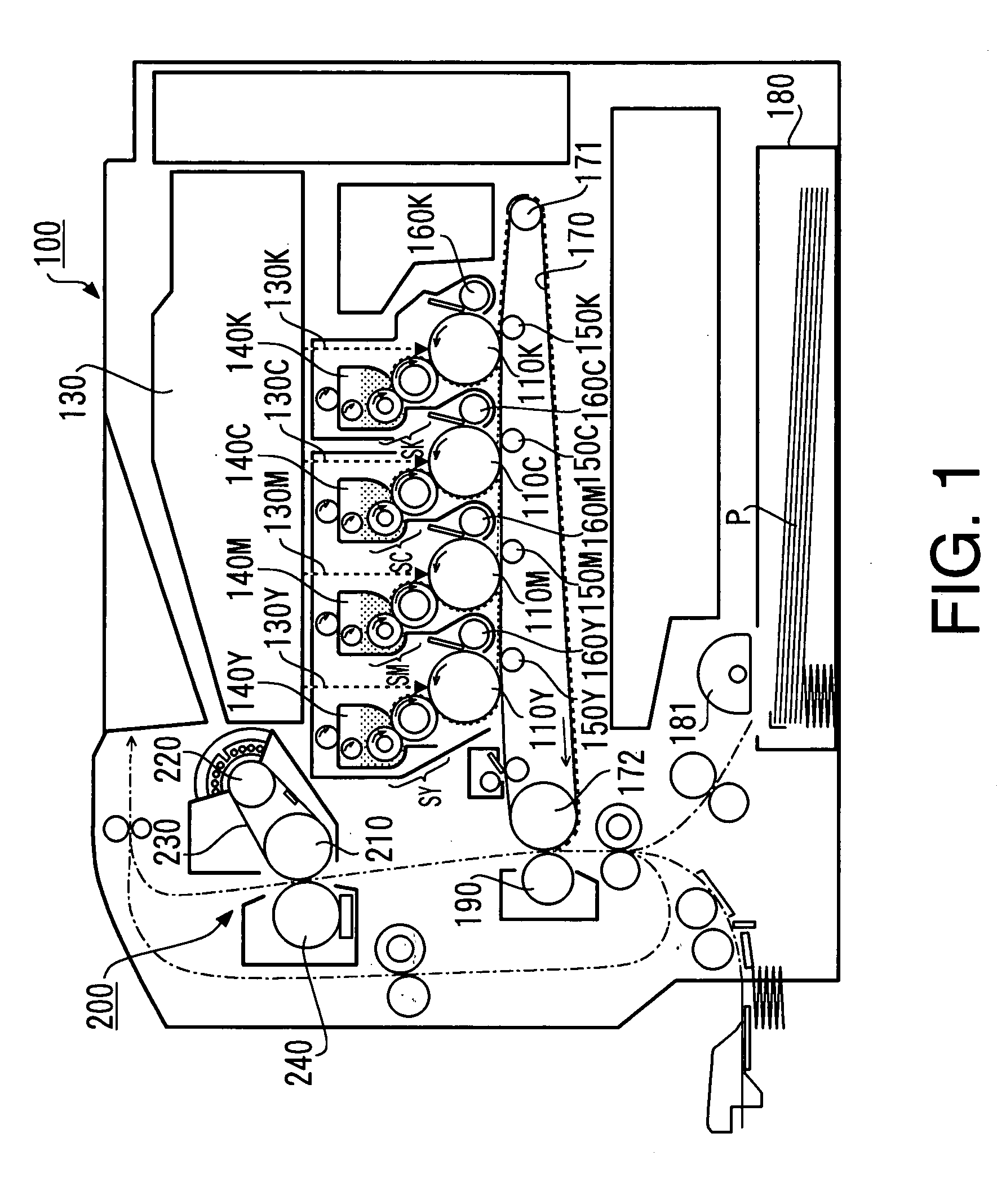
[0036]FIG. 1 is a schematic cross-sectional view showing the configuration of an image formation apparatus using an image heating apparatus according to Embodiment 1 of the present invention as a fixing apparatus. The image formation apparatus 100 shown in FIG. 1 is an image formation apparatus based on a 1-path scheme. In the image formation apparatus 100, toner images of four colors contributing to the coloring of a color image are individually formed on four image carriers, primary-transferred onto an intermediate transfer body overlapped on one another sequentially and then these primary transfer images are collectively transferred (secondary transfer) to a recording medium.

[0037] It goes without saying that the image heating apparatus according to this Embodiment 1 is not limited to only the 1-path scheme image formation apparatus, but can be mounted on all types of image formation apparatus.

[0038] In FIG. 1, suffixes Y, M, C, K of reference numerals assigned the respective c...

embodiment 2

[0088] Next, an image heating apparatus according to Embodiment 2 of the present invention will be explained. The image heating apparatus according to this Embodiment 2 has the same configuration as that of the aforementioned image heating apparatus according to Embodiment 1 except numerical values of various parameters of the aforementioned harness 300. Therefore, mainly the various parameters of the harness used in the induction heating apparatus of the image heating apparatus according to this Embodiment 2 will be explained here.

[0089] The numerical values of various parameters of the harness used in the induction heating apparatus of the image heating apparatus according to this Embodiment 2 are as follows: [0090] (1) Length of harness section (corresponding to 2 wires) 1.2 m [0091] (2) Wire diameter: 150×10−6 m [0092] (3) Wire cross section: 1.77×10⁻⁸ m2 [0093] (4) Number of wires: 80 [0094] (5) Harness cross section: 1.41×10⁻⁶ mm2 [0095] (6) Wire specific resistance: 1.81×10−...

embodiment 3

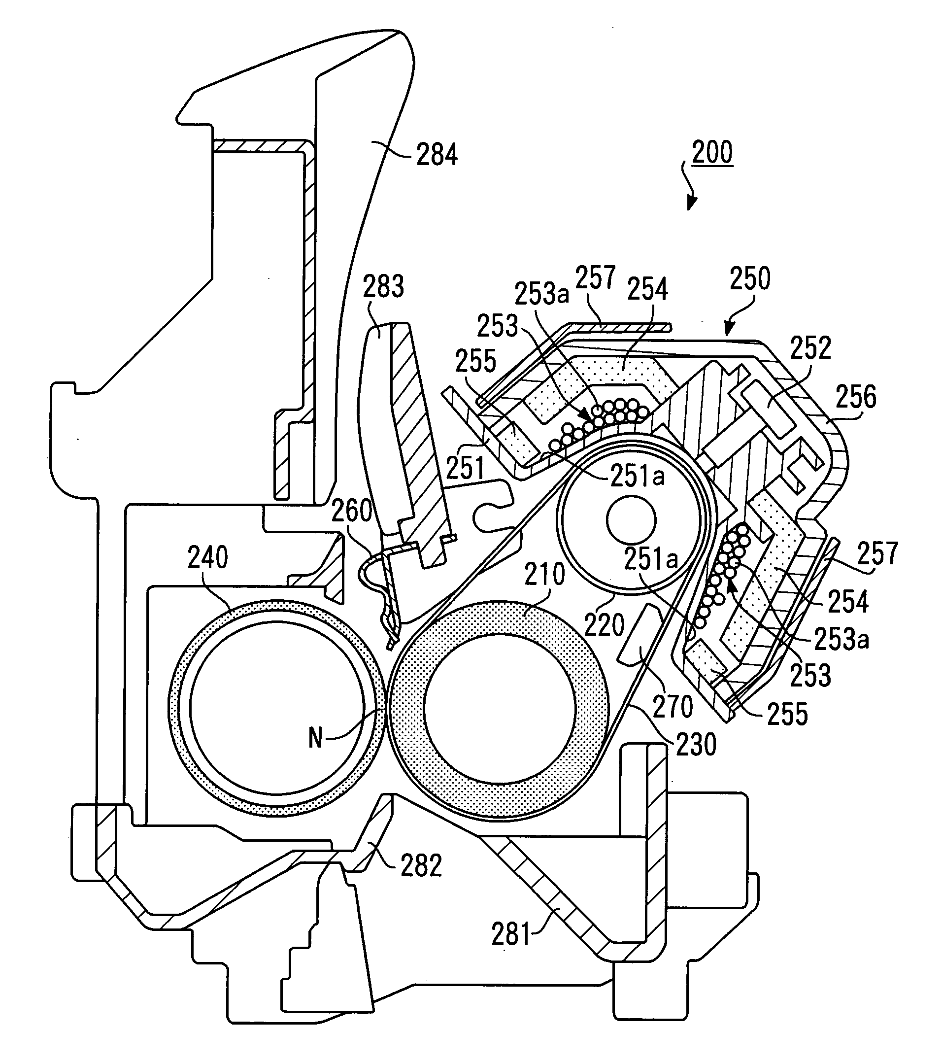
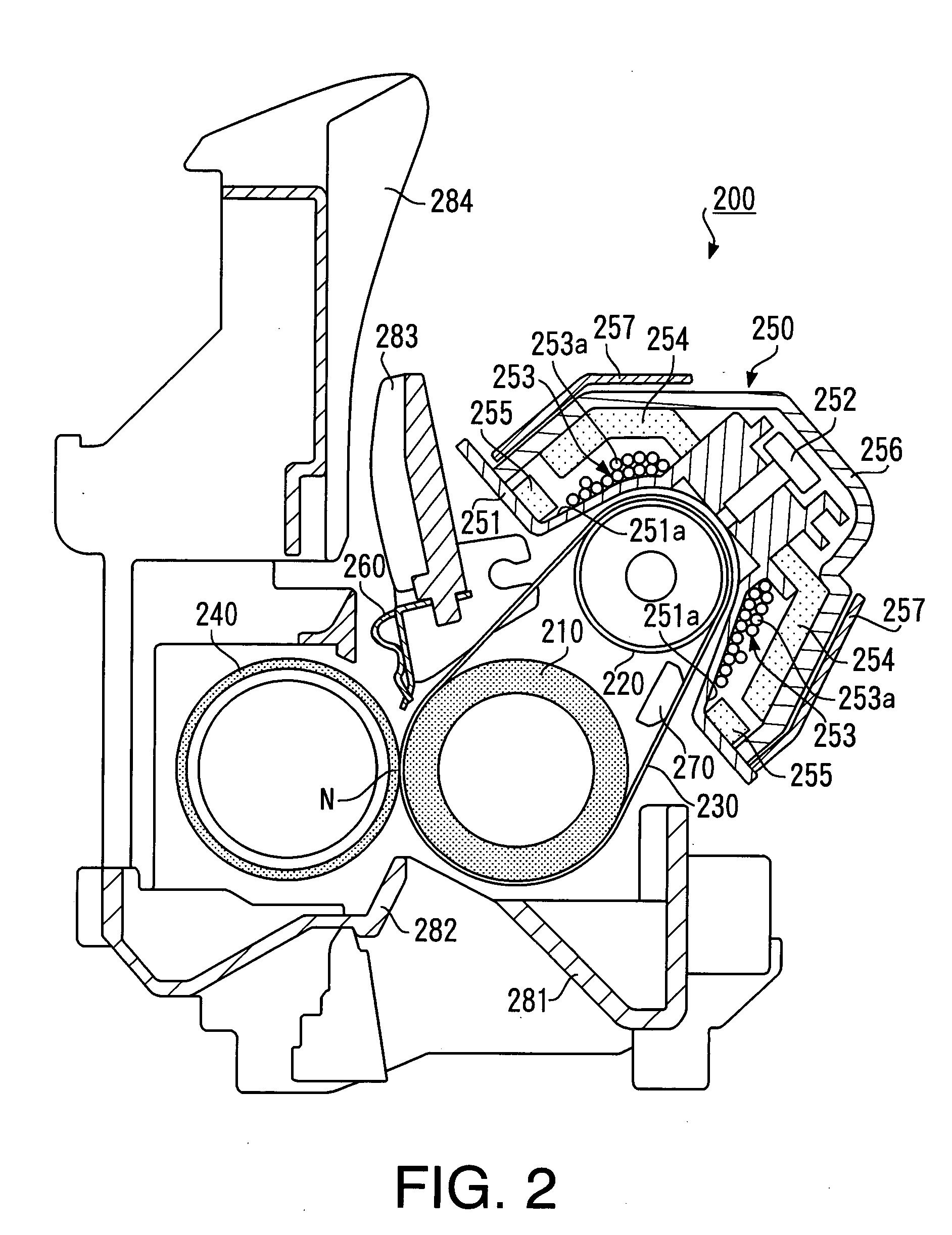
[0099] According to this embodiment, as shown in FIG. 2 and FIG. 3, the excitation coil 253 is constructed by alternately winding the coil wire 253a thereof around the coil support surface 251a of the support frame 251 so as to move along the axial direction of the heat generating roller 220. The length of the winding part of this excitation coil 253 is set to substantially the same length as the length of the area where the fixing belt 230 contacts the heat generating roller 220.

[0100] Here, as shown in FIG. 2 and FIG. 7, the support frame 251 wound with the excitation coil 253 is curved so as to cover the heat generating roller 220 and the coil support surface 251a wound with the coil wire 253a of the excitation coil 253 is curved and inclined.

[0101] For this reason, in the induction heating apparatus 250 in such as configuration, when the coil wire 253a is wound around the support frame 251, the coil wire 253a is likely to slide in the direction indicated by an arrow in FIG. 7,...


PUM

PropertyMeasurementUnit
Lengthaaaaaaaaaa
Thicknessaaaaaaaaaa
Thicknessaaaaaaaaaa

Abstract

The present invention provides an induction heating apparatus including a fixing belt that heats an unfixed image on recording paper, an excitation coil that induction-heats the fixing belt, an inverter circuit that supplies power to the excitation coil, a harness that electrically connects the excitation coil and the inverter circuit. The harness is constructed of a litz wire having a resistance of the harness section of 0.016 Ω or below formed by stranding several tens of wires which are conductive wires coated with an insulator into a predetermined thickness.

Description

BACKGROUND OF THE INVENTION [0001] 1. Field of the Invention [0002] The present invention relates to an image heating apparatus based on an induction heating scheme which heats an unfixed image on a recording medium, and more particularly, to an image heating apparatus effectively applicable to a fixing apparatus for an image formation apparatus such as a copier, facsimile and printer based on an electrophotography scheme or electrostatic recording scheme. [0003] 2. Description of the Related Art [0004] As a heating section of an image heating body which heats / fixes an unfixed image on a recording medium such as transfer paper and an OHP (Over Head Projector) sheet, an image heating apparatus based on an induction heating (IH; induction heating) scheme is known. [0005] This image heating apparatus based on an IH scheme generates an eddy current by causing a magnetic field generated by a magnetic field generation section to act on the image heating body and heats / fixes an unfixed ima...

Claims


Application Information

Patent Timeline
IPC IPC(8): H05B6/14
CPCG03G15/205H05B6/145G03G15/2053
Inventor SAMEI, MASAHIRONOGUCHI, TOMOYUKI
Owner PANASONIC CORP
Why Eureka
Try Eureka