Light-emitting device with high heat-dissipating efficiency

a technology of heat dissipation efficiency and light-emitting device, which is applied in the direction of semiconductor devices, electrical equipment, basic electric elements, etc., can solve the problems of low light-emitting efficiency the light-emitting diode provides, and the permanent damage of the light-emitting die, so as to reduce manufacturing costs, ensure operation safety, and high heat dissipation efficiency

Inactive Publication Date: 2005-09-15
OPTO TECH
View PDF7 Cites 87 Cited by
  • Summary
  • Abstract
  • Description
  • Claims
  • Application Information

AI Technical Summary

Benefits of technology

[0007] Thus, it is a keynote of the present invention to devise a novel light-emitting device with high heat-di

Problems solved by technology

Moreover, the higher operating temperature the light-emitting die has, the lower light-emitting efficie

Method used


Image

  • Light-emitting device with high heat-dissipating efficiency
  • Light-emitting device with high heat-dissipating efficiency
  • Light-emitting device with high heat-dissipating efficiency

Examples


Embodiment Construction

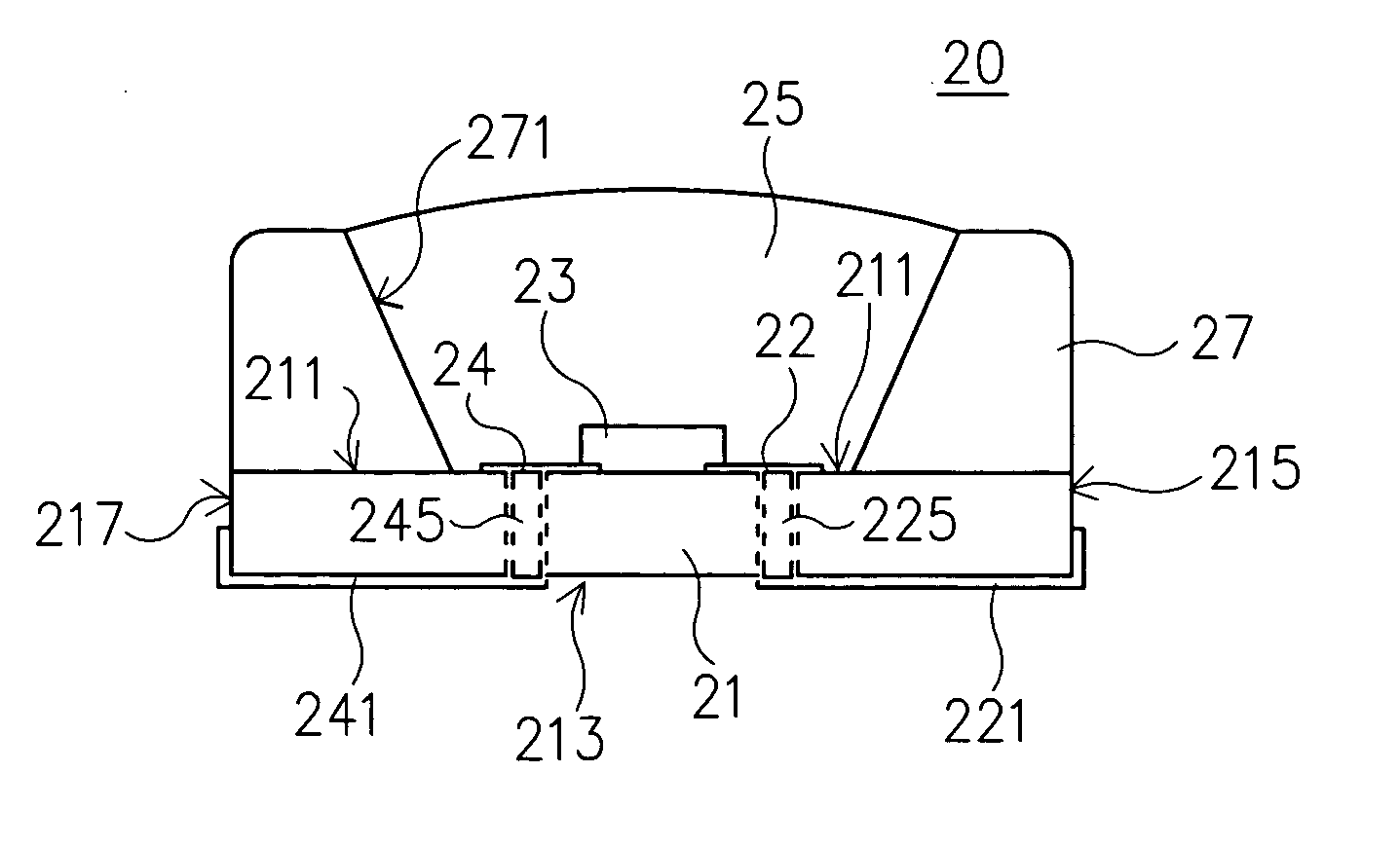
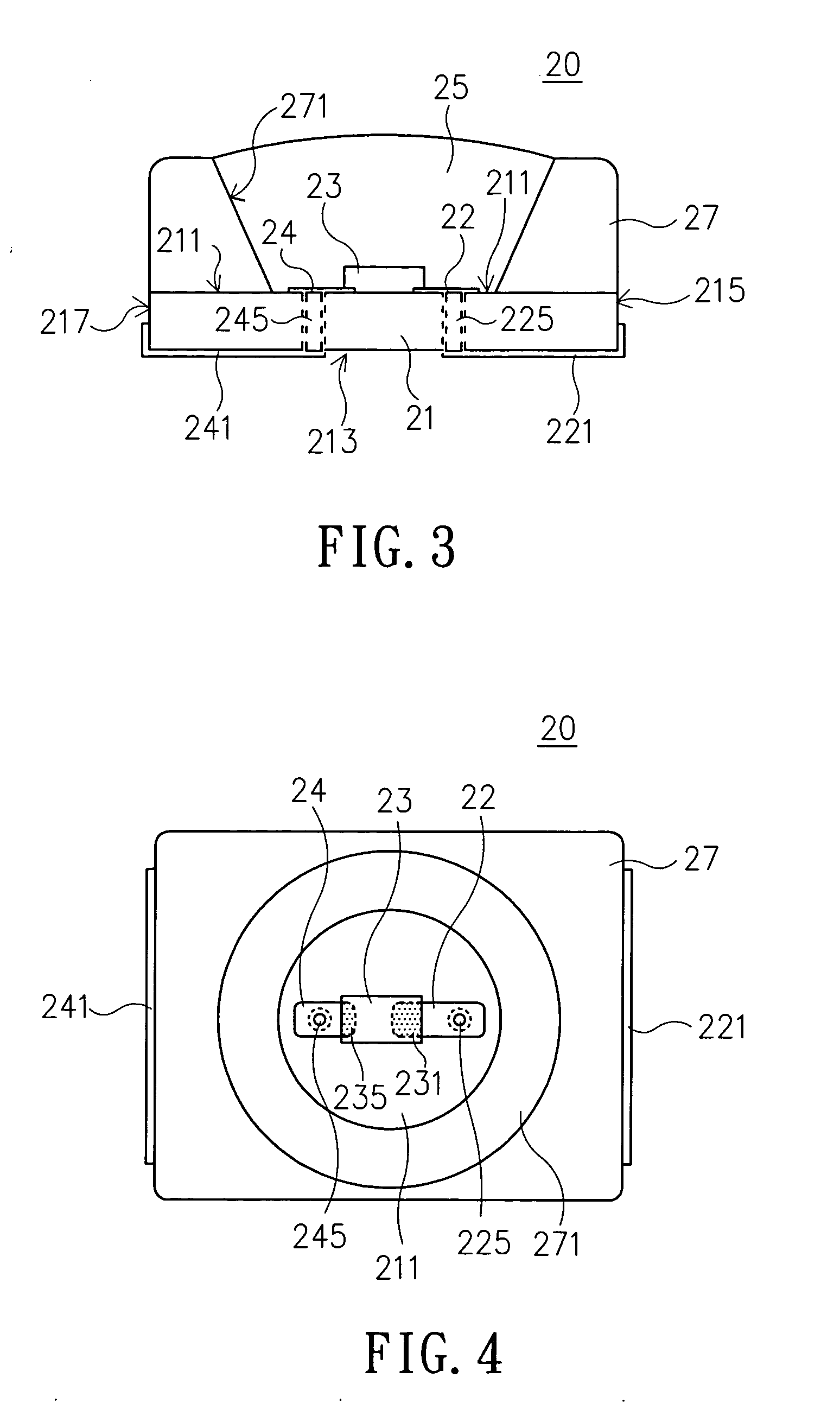
[0019] Referring to FIG. 3 and FIG. 4, a side view and a top-view of the light-emitting device according to a preferred embodiment of the present invention are respectively illustrated. As shown, a light-emitting device 20 with high heat-dissipating efficiency according to the present invention includes a substrate 21, at least one light-emitting die 23 fixedly mounted on the top surface 211 of the substrate 21, and an optical reflector 37 adjacently surrounding the light-emitting die 21 and fixedly mounted on the substrate 21.

[0020] In addition, a pair of power-supply circuits 22,24 are directly mounted on the substrate 21 and protrude from the substrate 21 via perforations 225 and 245, and further extends to the bottom surface 213 and the side surfaces 215,217 to form external electrodes 221,241. The light-emitting die 23 is fixedly mounted on the top surface 211 of the substrate 21 by the flip-chip mounting, and the two electrodes 231,235 are electrically connected to a correspo...


PUM


Abstract

A light-emitting device with high heat-dissipating efficiency, includes a ceramic substrate having at least one pair of power-supply circuits mounted at a specific location of the substrate, a light-emitting die fixedly mounted on the ceramic substrate by flip-chip mounting, wherein the two electrodes of the light-emitting die are electrically connected to a corresponding power-supply circuit, respectively, and an optical reflector which is adjacently mounted in the periphery of the light-emitting die and made up of a metallic material or a material with a high coefficient of thermal conductivity for increasing the heat-dissipating area and providing a light-guiding mechanism.

Description

FIELD OF THE INVENTION [0001] The present invention is related to a light-emitting device, and more particularly to a light-emitting device with high heat-dissipating efficiency, including an optical reflector incorporating the capabilities of light-guiding and heat-dissipating for increasing the heat-dissipating area and providing the light-guiding capability. BACKGROUND OF THE INVENTION [0002] As is well known in the prior art, a light-emitting diode has been widely employed in computer peripherals, communication products, and other electronic device because of its light weight, low power consumption, and prolonged longevity. [0003] For a high-power light-emitting diode, especially a light-emitting diode serving for the purpose of illumination, the operating current of the light-emitting diode has to be increased or the dimension of the light-emitting die has to be upgraded in order to provide a better illumination. [0004] However, with the increase of the operating current of the...

Claims


Application Information

Patent Timeline
IPC IPC(8): H01L29/22H01L31/00
CPCH01L33/486H01L33/60H01L33/642H01L33/644H01L2224/48247H01L2224/48091H01L2924/00014
Inventor LIN, MING-DERLIN, SAN BAO
Owner OPTO TECH
Why Eureka
Try Eureka