Lamp with metal grid radiator for heat dissipation

a radiator and metal grid technology, applied in the field of lamps, can solve the problems of limiting permanent damage to inability to efficiently remove the heat generated in the light emitting device, so as to increase the light intensity of the lamp and remove the heat generated in the lamp

Inactive Publication Date: 2005-09-15
WU JIAHN CHANG
View PDF6 Cites 12 Cited by
  • Summary
  • Abstract
  • Description
  • Claims
  • Application Information

AI Technical Summary

Benefits of technology

[0006] An object of this invention is to increase the light intensity of a lamp

Problems solved by technology

This prior art structure has the drawback that the heat generated in the light emitting devices cannot be removed efficiently.
For increased light emission, the voltage applied to the light emitting devices m

Method used


Image

  • Lamp with metal grid radiator for heat dissipation
  • Lamp with metal grid radiator for heat dissipation
  • Lamp with metal grid radiator for heat dissipation

Examples


second embodiment

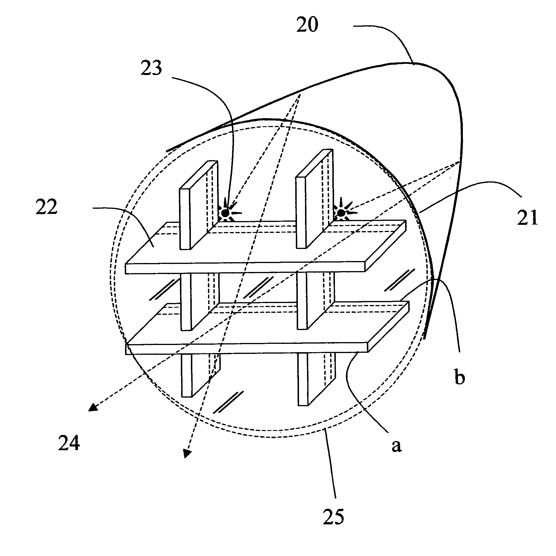
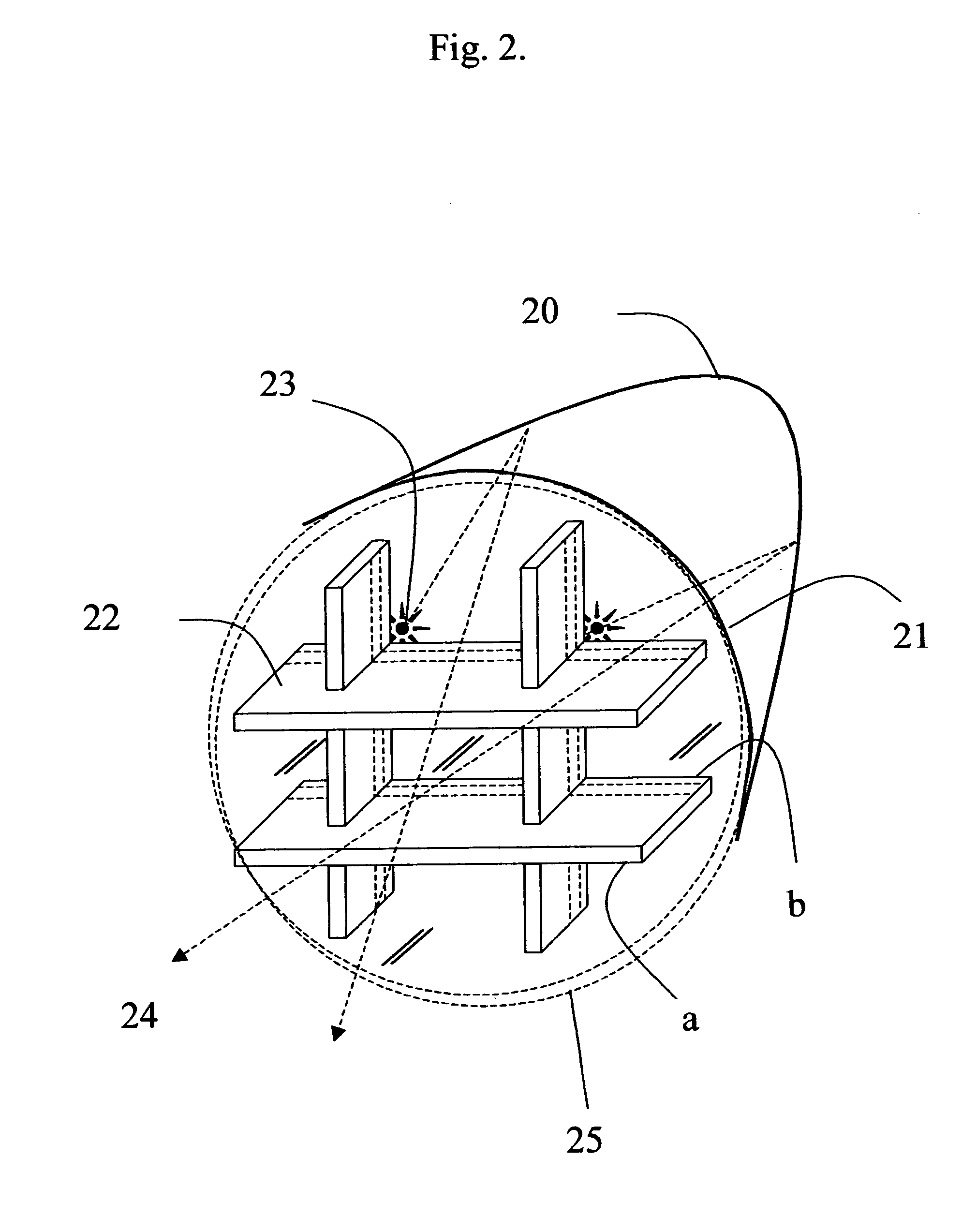
[0015]FIG. 3 shows the invention. In this invention, the metal grid radiator 22 with open grid, i.e. without any back-filled transparent material in the grid is placed toward the open end 21 of the cup 20, with outer surfaces “a” and inner surfaces “b”. The light emitting device 26 is placed at the bottom of the cup such as the focal point. The light emitted from the light emitting device 26 can be transmitted through the windows of the metal grid either directly or reflected from the inner wall of the cup as emitting rays 24.

third embodiment

[0016]FIG. 4 shows the invention. The structure is similar to that in FIG. 3 with reference numbers denoting corresponding parts. The windows of the metal grid 22 is backfilled with glass or polymer transparent composite to prevent any dust from entering the cup.


PUM

PropertyMeasurementUnit
Transparencyaaaaaaaaaa
Heataaaaaaaaaa

Abstract

A metal grid is placed in the open end of a cup-shaped light bulb as a radiator to dissipate the heat generated from the light emitting device. One or more light emitting devices can be placed on the inner side surface of the metal grid, and the light emitted from the light emitting devices is reflected by the inner surface of the cup and transmitted through the windows in the metal grid. The horizontal plates of the metal grid and the vertical walls of the grid can be insulated from each other to serve as electrodes for the light emitting device. The cup can be back-filled with glass or other transparent polymer composite to prevent dust from entering the cup. Alternatively, a single light emitting device is place near the bottom of the cup

Description

BACKGROUND OF THE INVENTION [0001] 1. Field of the Invention [0002] This invention relates to lamps, particularly to a radiator for lamps for more effective heat removal. [0003] 2. Brief Description of Related Art [0004]FIG. 1 shows a prior art lamp. Two light emitting devices 11, 12 are mounted inside a cup 17. Each light emitting device has a bottom electrode anchored in the cup which is connected to a lead 14a, and a top electrode wire-bonded to leads 14b, 14c. The light emitting devices are sealed in a glue 16 for protection and reliability. [0005] This prior art structure has the drawback that the heat generated in the light emitting devices cannot be removed efficiently. For increased light emission, the voltage applied to the light emitting devices must be increased, generating more heat, which may cause permanent damage to the light emitting device. This kind of structure has limited heat dissipating area and hence limits the light intensity of the lamp. SUMMARY OF THE INVEN...

Claims


Application Information

Patent Timeline
IPC IPC(8): F21V9/00
CPCF21V3/0418F21V3/0436F21V7/0008F21V29/89F21V29/773F21V29/83F21V11/06F21V3/062F21V3/061
Inventor WU, JIAHN-CHANG
Owner WU JIAHN CHANG
Why Eureka
Try Eureka