Penlight and touch screen data input system and method for flat panel displays

Inactive Publication Date: 2005-09-15
INTEGRATED DEVICE TECH INC
View PDF53 Cites 120 Cited by
  • Summary
  • Abstract
  • Description
  • Claims
  • Application Information

AI Technical Summary

Benefits of technology

[0010] This invention provides system, display device, pixel and sensor architecture, and methods for receiving or sensing contact and non-contact inputs (such as a light pen input) to the surface of an emissive display device, and more particularly to systems, devices, a

Problems solved by technology

Assembly and maintenance costs may also typically increase.
All of these additional components add to the cost of the device and where competition is high and profit margins small, the additional cost is unwelcome.
In some devices the cost of adding a touch panel to a display panel may double the cost as compa

Method used


Image

  • Penlight and touch screen data input system and method for flat panel displays
  • Penlight and touch screen data input system and method for flat panel displays
  • Penlight and touch screen data input system and method for flat panel displays

Examples


Example

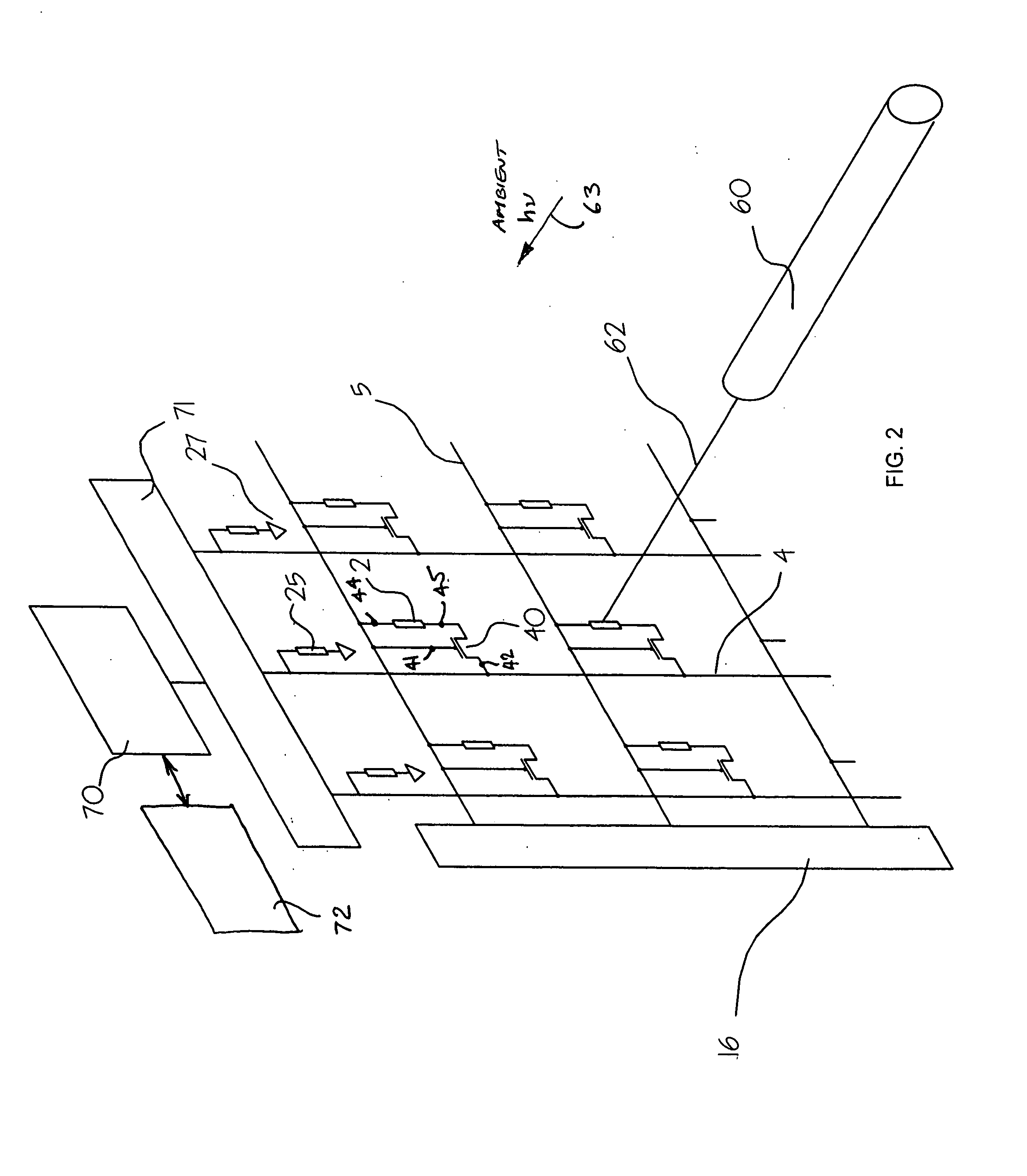
[0046] In a second embodiment, the human finger can be used to shadow the sensor array from ambient light. This would be a relatively coarse input system, but accurate enough for activating icons on the display. Furthermore, the ambient light would need to be of sufficient intensity on the display that the shadow was detectable relative to unshadowed sensors.

Example

[0047] In a third embodiment, the phenomenon of total internal reflection in plate is utilized. It is known that light entering the edge of a plate made from any transparent material in a wide range of optical densities (indices of refraction) will travel from one side of the plate to the other without light exiting the top and bottom faces of the plate provided the optical densities of the plate and the materials in contact with the plate are properly selected. Ordinary glass surrounded by transparent materials of higher optical density work well. Thus, a plate of glass or methylmethacrylate plastic can be attached to the front of the OLED display and sensor array. Red LEDs can direct light into one side of the plate without any LED light impinging on the sensors array because absent some disturbance the light will propagate entirely within the plate. If, however, on object is touched to the plate, the change in optical interface between the two materials will be sufficient to caus...

Example

[0048] In a fourth embodiment, an image may be input rather than merely a location on the screen. For example, the image of a finger print can be input to the optical sensor array and captured by placing the image on the surface of the display glass (such as by using ink or by picking up the moisture or oils from the finger) and shadowing light through that image from any source of external light. It will be appreciated that the resolution increases if collimated light is used as the external source. In an alternative to this direct input, a system may be implemented in which a thin material such as cellophane can be attached to the front of the display with a dispensing roll on one side and a take-up spool on the other side. Between the cellophane and display glass is provided an optical medium such as glycerin which matches the optical density of the scattering plate. The cellophane rides on or within a glycerin layer that contacts both the scattering plate and the cellophane. Thi...


PUM


Abstract

System, device, and method for receiving or sensing touch or light input to an emissive display such as to a OLED display using the same or different sensors as are used to sense and maintain a pixel luminance. Penlight and touch screen data input system and method for display. A sidelight illuminated display and touch panel input device. Method and device for reading display pixel emission and ambient luminance levels. Emissive display having sensing for luminance stabilization and user light or touch screen input. Method and device for emissive display using shielded or partially shielded sensors. Emissive pixel display device characterized in that photon sensors are disposed within pixels and operated to sense photons emitted by emitter within pixel and ambient photons emitted by sources outside pixel, sensed internally emitted photons being for luminance feedback control and sensed ambient photons being used to detect external light source or sources.

Description

RELATED APPLICATIONS [0001] This application claims the benefit of priority under 35 U.S.C. §119 and / or 35 U.S.C. §120 to the following applications: U.S. Provisional Patent Application Ser. No. 60 / 547,358 filed on 24 Feb. 2004 and entitled Penlight and Touch Screen Data Input System for Flat Panel Displays; U.S. Provisional Patent Application Ser. No. 60 / 583,744 filed 29 Jun. 2004 and entitled High-Impedance to Low-Impedance Conversion; and to U.S. Utility patent application Ser. No. 11 / 015,638 filed 17 Dec. 2004 and entitled Feedback Control System and Method for Operating a High-Performance Stabilized Active Matrix Emissive Display; each of which applications is hereby incorporated by reference. [0002] This application is also related to U.S. Utility patent application Ser. No. ______ (Atty. Docket 34135 / US2) filed 8 Feb. 2005 and entitled PENLIGHT AND TOUCH SCREEN DATA INPUT SYSTEM AND METHOD FOR FLAT PANEL DISPLAYS; U.S. Utility patent application Ser. No. ______ (Atty. Docket ...

Claims


Application Information

Patent Timeline
IPC IPC(8): G06F3/038G06F3/041G06F3/042G09G3/30G09G3/32H01L27/144H01L27/32H05B37/02
CPCG06F3/03542H01L2251/5315G06F3/0412G06F3/042G06F2203/04109G09G3/3233G09G3/3275G09G3/3291G09G2300/0819G09G2300/0842G09G2300/0852G09G2310/066G09G2320/0233G09G2320/029G09G2320/0295G09G2320/043G09G2320/045G09G2320/0693G09G2360/142G09G2360/147G09G2360/148H01L27/1446H01L27/288H01L27/3227H01L27/323H01L27/3269H01L27/3272G06F3/0386H10K65/00H10K59/60H10K59/40H10K59/13H10K59/126H10K2102/3026
Inventor NAUGLER, W. EDWARD JR.REDDY, DAMODER
Owner INTEGRATED DEVICE TECH INC
Why Eureka
Try Eureka