
Multi-purpose imaging apparatus and adaptors therefor

a multi-purpose, imaging technology, applied in the direction of instruments, television systems, fluorescence/phosphorescence, etc., can solve the problems of high cost of medical diagnosis instruments, high cost of patient purchase, and unrealistic cost of diagnosis instruments

Active Publication Date: 2005-09-15
TELEMEDC LLC
View PDF13 Cites 40 Cited by
  • Summary
  • Abstract
  • Description
  • Claims
  • Application Information

AI Technical Summary

Benefits of technology

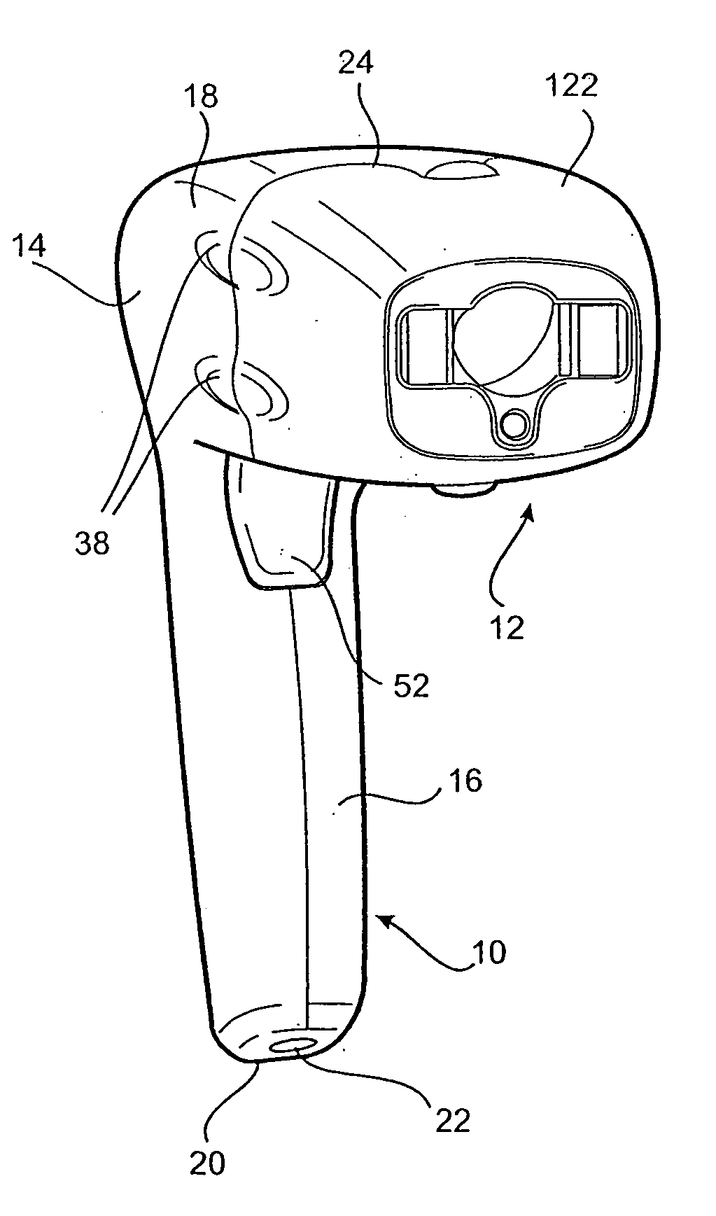
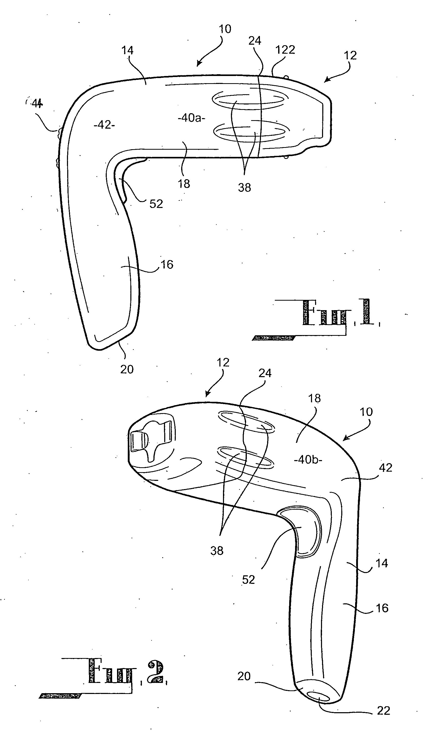
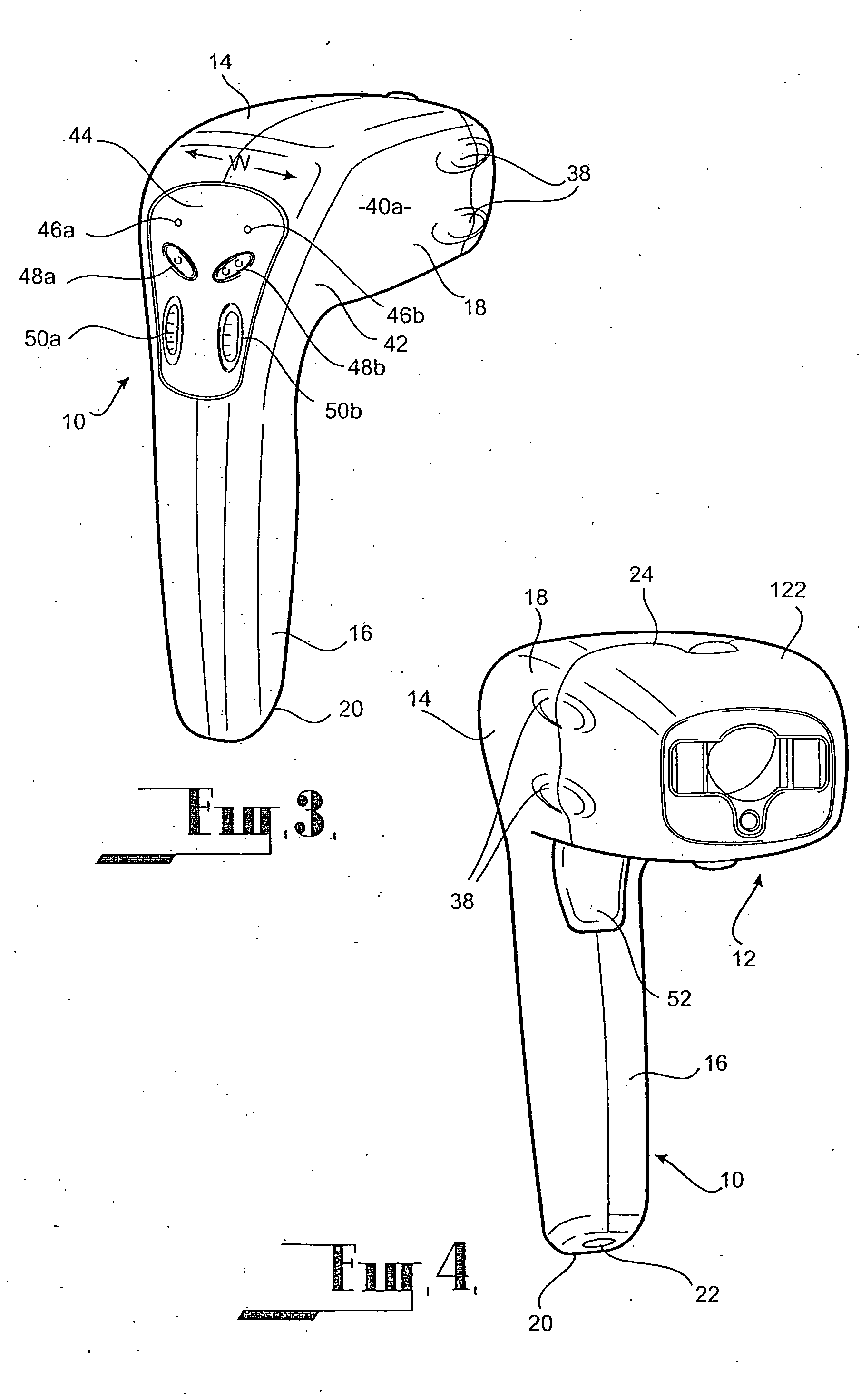
[0008] The present invention seeks to provide a multi-purpose imaging apparatus and adaptors therefor. The optical configuration of the adaptors allow the multi-purpose imaging apparatus to perform a variety of diagnostic activities.
[0009] In this manner, the number of patients capable of being serviced by the multi-purpose imaging apparatus is increased. At the same time the versatility of the multi-purpose imaging apparatus makes it more affordable for such regions as the cost of the device can be spread against a number of health-service providers.
[0010] Ideally, the imaging means used in the multi-purpose imaging apparatus is a digital camera. Use of the digital camera is preferred as digital images are instantaneous and available in a form that allows for rapid transmission or modification as may be required. Digital images are also preferred as the can be stored on removable media.
[0011] The multi-purpose imaging apparatus also includes a simplified control structure, by which the optics of the adaptors can be controlled. This level of control extends beyond simply controlling activation of light sources contained within the adaptor and includes controlling the brightness of such light sources. The use of a simplified control structure allows people not specifically trained as medical professionals to easily operate the device in a manner that allows images taken with the apparatus to then be used by medical professionals to give an informed diagnosis.
[0012] The invention provides further advantages due to its portability. This has been achieved by both providing a case for holding the various components of the multi-purpose imaging system and by adapting the multi-purpose imaging apparatus to be held comfortably in the hand of the operator.

Problems solved by technology

Commercial medical diagnosis instruments are generally expensive to purchase.
In remote or sparsely populated regions, the cost of purchasing the diagnosis instruments may be commercially unrealistic when weighed against the number of people such instruments will service.
This means that the patient has to travel to a remote service provider in order to be diagnosed via such instruments.
This can then be costly for the patient, both in monetary terms and possibly in health terms.
Even in situations where the above problem does not exist, there may still be the problem of the lack of specialist expertise necessary to properly operate such instruments.
However, the portable slit lamp described is limited in its diagnostic capabilities—the portable slit lamp only providing functionality for imaging the anterior segment of the eye.

Method used


Image

  • Multi-purpose imaging apparatus and adaptors therefor
  • Multi-purpose imaging apparatus and adaptors therefor
  • Multi-purpose imaging apparatus and adaptors therefor

Examples


case 606

[0117] Case 606 has a built-in power transformer 616. The power transformer 616 provides power to the tablet PC 608 via cable 618. For ease of use, power transformer 616 has a power connector 620 built into a sidewall 622 of the case 606. The power connector 620 in the embodiment shown is adapted to receive a standard 3-pin power cable (not shown). The power connector 620 also includes a power switch 624 for turning the power transformer 616 on or off.

[0118] In addition to providing power to the tablet PC 608, power transformer 616 is attached to a battery (not shown) built into case 606. This battery provides additional power to the tablet PC 608 as needed.

[0119] Use of the multi-purpose imaging apparatus 10 will now be described in the context of the multi-purpose imaging system 600 described above.

[0120] Case 606 is opened to reveal the multi-purpose imaging apparatus 10, adaptors 12 and tablet PC 610. Tablet PC 610 is then pivoted about pivot point 612 until it reaches a posit...

second embodiment

[0176] In yet still further alternative arrangements of the second embodiment, the USB connection may be replaced with a Firewire™ connector. Alternatively, all forms of physical connection may be omitted, the multi-purpose processing apparatus 10 being able to communicate with tablet PC 610 via wireless means.


PUM


Abstract

Provided is a multi-purpose imaging apparatus (10) comprising a body (14) and imaging means (36) housed within the body (14). The body (14) is adapted to releasably engage an adaptor (12). The adaptor (12) has an aperture (108) extending therethrough that aligns with the optical axis (X) of the imaging means (36) when so engaged, such that at least a portion of the optical axis (X) is not obscured. The adaptor (12) also has optics for illuminating a subject within the optical axis (X) for diagnostic purposes.

Description

CROSS REFERENCE TO RELATED APPLICATIONS [0001] This application is a continuation-in-part of International Application No. PCT / AU03 / 00564, filed on May 8, 2003, published as WO 03 / 094706 on Nov. 20, 2003, and claiming priority to Australian application PS 2190, filed on May 8, 2002. [0002] All of the foregoing applications, as well as all documents cited in the foregoing applications (“application documents”) and all documents cited or referenced in the application documents are incorporated herein by reference. Also, all documents cited in this application (“herein-cited documents”) and all documents cited or referenced in herein-cited documents are incorporated herein by reference. In addition, any manufacturer's instructions or catalogues for any products cited or mentioned in each of the application documents or herein-cited documents are incorporated by reference. Documents incorporated by reference into this text or any teachings therein can be used in the practice of this inv...

Claims


Application Information

Patent Timeline
IPC IPC(8): G01N21/64A61B1/227A61B1/233A61B1/24A61B3/00A61B3/10A61B3/12A61B3/135A61B3/14A61B5/00A61B5/103G03B15/00G03B15/02G03B17/56H04N5/225
CPCA61B1/00105H04N5/225A61B1/24A61B3/0075A61B3/1208A61B3/135A61B3/185A61B5/0071A61B5/0088A61B5/441A61B2560/0431A61B1/0638A61B1/043A61B1/0607A61B1/0684A61B1/227H04N23/00
Inventor YOGESAN, KANAGASINGAMCONSTABLE, IANSUPLEWSKI, GABRIELGUILLON, JEAN-PIERRE
Owner TELEMEDC LLC
Learn More