High precision beamsteerer based on fixed beamforming approach beampatterns

a beamforming and beam pattern technology, applied in the field of beamsteering, can solve the problems of prior art sound localization systems, difficult to create a main beam with a very narrow beam angle, and underestimate the bearing of a source, and achieve the effect of reasonable error robustness and high angular resolution

Active Publication Date: 2005-09-15
MITEL
View PDF17 Cites 19 Cited by
  • Summary
  • Abstract
  • Description
  • Claims
  • Application Information

AI Technical Summary

Benefits of technology

[0015] According to the present invention, a beamsteerer is provided for steering a narrow null toward a domain of interest. The lowest energy point corresponds to the location of a source of audio. The beamsteerer uses an array of only a few sensors that are compact, and provides a null with high angular resolution and reasonable error robustness (e.g. a resolution finer than 5 degrees).

Problems solved by technology

Estimating the bearing of a source is a problem for applications such as passive sonar (in underwater antenna alignment) and in video conferencing (speaker location).
There are two principal disadvantages of prior art sound localization systems, as set forth above.
Firstly it is very difficult to create a main beam with a very narrow beam angle, giving rise to expensive solutions in order to achieve high resolution.
Secondly, such highly directional beam patterns are generally accompanied by significant side lobes, which can lead to erroneous look directions.
A source locator based on such a beamformer cannot efficiently discriminate side reflections.
Because the audio detection mechanism is limited in its ability to detect sound, a special camera is used to enhance the peripheral portion of the field of view.
The major difficulties in these systems are that there is a need for very accurate knowledge of the position of the sensors, and the sensors must be spaced apart by a significant distance to obtain a reasonable time delay from one sensor to another.
However, this approach requires intensive computation and a large array.
These devices are also critically affected by phase and amplitude errors.

Method used


Image

  • High precision beamsteerer based on fixed beamforming approach beampatterns
  • High precision beamsteerer based on fixed beamforming approach beampatterns
  • High precision beamsteerer based on fixed beamforming approach beampatterns

Examples


Embodiment Construction

I. Microphone Configuration

[0032] In the preferred embodiment, the frequency range of operation is between 1000-1500 Hz in air (wavelength: 0.22[0033] 1. The background noise level diminishes with frequency. [0034] 2. The speech intelligibility is reasonably important in this band. [0035] 3. Reverberation also diminishes with frequency although it is important in the low end of the chosen interval.

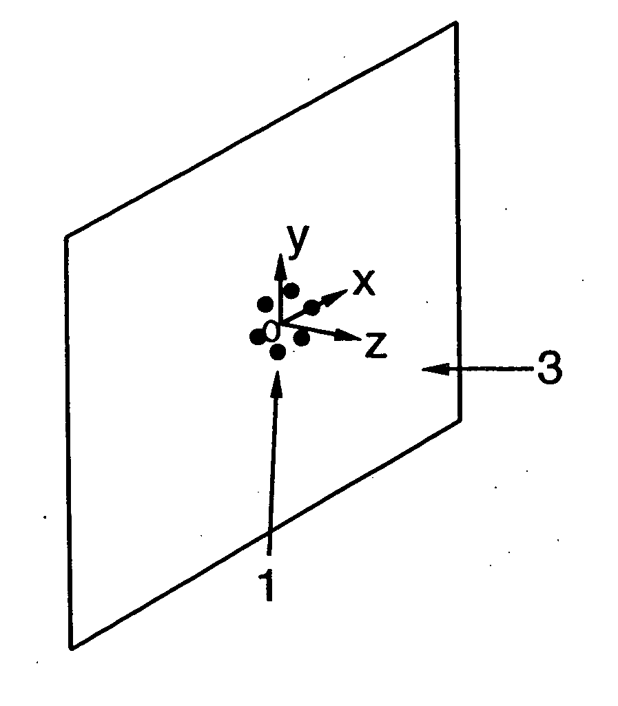
[0036] The simplest embodiment of the inventive beamsteerer is implemented in an audio-video conferencing system as shown in FIG. 1, comprising a planar microphone array 1 on a reflecting plane 3. Ideally, the reflecting plane 3 is a wall toward which most of the participants look during an audio-video conference (e.g. a video screen above which a video camera (not shown) is placed). The microphone spacing is selected to respect the well known λ / 2 criterion. The two-dimensional array 1 is capable of providing a unique null in a plane normal to the plane 3 of the array (i.e. in the directi...


PUM


Abstract

A beamsteerer for broadband energy source location, comprising an array of sensors, each for generating a signal vector within one of a plurality of sectors in a domain of interest, and a beamformer for receiving and multiplying each signal vector by a set of optimal weight vectors to generate a plurality of beampatterns, each of the beampatterns being characterized by a null having high angular resolution, and detecting the source by selecting a maximum steering index.

Description

FIELD OF THE INVENTION [0001] The invention relates generally to sensor arrays, and more particularly to a beamsteerer for high precision, broadband sound source location in an audio-video conference system, which ignores sound reflections off of walls. BACKGROUND OF THE INVENTION [0002] Estimating the bearing of a source is a problem for applications such as passive sonar (in underwater antenna alignment) and in video conferencing (speaker location). The use of sensor arrays is well known in the art for addressing this problem. In one approach, the array information is used to synthesize a beam that is aimed at various points in a domain of interest. An estimate of the source location is derived from the point of maximum received energy. [0003] N. Strobel, S. Spors & R Rabenstein “Joint Audio-Video Signal Processing for Object Localization and Tracking”, Chapter 10 in Microphone Arrays by Branstein & Ward, Springer, 2001, discusses a number of sophisticated methods for sound source...

Claims


Application Information

Patent Timeline
Patent Type & Authority Applications(United States)
IPC IPC(8): G01S3/00G01S3/80G01S3/805G01S3/808G10K11/34H04N5/232H04R1/32H04R3/00H04R29/00
CPCG01S3/8006H04R3/005G10K11/348G10K11/346
Inventor DEDIEU, STEPHANEMOQUIN, PHILIPPE
Owner MITEL
Why Eureka
Try Eureka