Object lens producing device and producing method

a technology of producing device and producing method, which is applied in the direction of instruments, recording information storage, disposition/mounting of heads, etc., can solve the problems of inability to accurately condensate light beam radiated from light source on the signal recording surface, and it is extremely time-consuming to adjus

Inactive Publication Date: 2005-09-15
SONY CORP
View PDF9 Cites 11 Cited by
  • Summary
  • Abstract
  • Description
  • Claims
  • Application Information

AI Technical Summary

Benefits of technology

[0015] It is therefore an object of the present invention to provide a method and apparatus for producing a novel objective lens unit, whereby the deficiencies inherent to the aforementioned conventional technique may be overcome.
[0016] It is another object of the present invention to provide a method and apparatus for producing a novel objective lens unit, whereby an objective lens unit, with a numerical aperture not less than 0.7, which is made up by plural objective lenses, in which the relative positions of the lenses may be adjusted to high accuracy and in which it is possible to suppress the generation of the spherical aberration, may be produced readily.

Problems solved by technology

In light of for example mold release properties, it is extremely difficult to form the objective lens unit having a non-spherical surface of a large curvature using a metal die.
Moreover, with an objective lens unit having a non-spherical surface of a larger curvature and a larger numerical aperture (NA), the light beam radiated from the light source cannot be condensed accurately on the signal recording surface even on occurrence of perturbations resulting from the slightest tilt relative to the optical axis.
With these methods, the phenomena observed are not changed independently for respective adjustment parameters, such that adjustment is extremely time-consuming due to many looped procedures required for achieving the final performance.
The lens secured in position in this manner in the lens holder with an adhesive is likely to undergo misregistration due to environmental changes, such as increasing temperature or humidity.
It is however extremely difficult to have the two lenses mounted within the lens holder as this high degree of accuracy is maintained.
Additionally, depending on the mounting environment, fine dust and dirt on the order of 1 μm tend to be intruded into a space between the step within the lens holder and the lens to render it difficult to maintain parallelism between the two lenses.
Although the spherical aberration of the lenses being adjusted may be measured using an interferometer, a complicated apparatus is needed, while the production cost is increased.

Method used


Image

  • Object lens producing device and producing method
  • Object lens producing device and producing method
  • Object lens producing device and producing method

Examples


Embodiment Construction

[0071] Referring to the drawings, preferred embodiments of the present invention will be explained in detail.

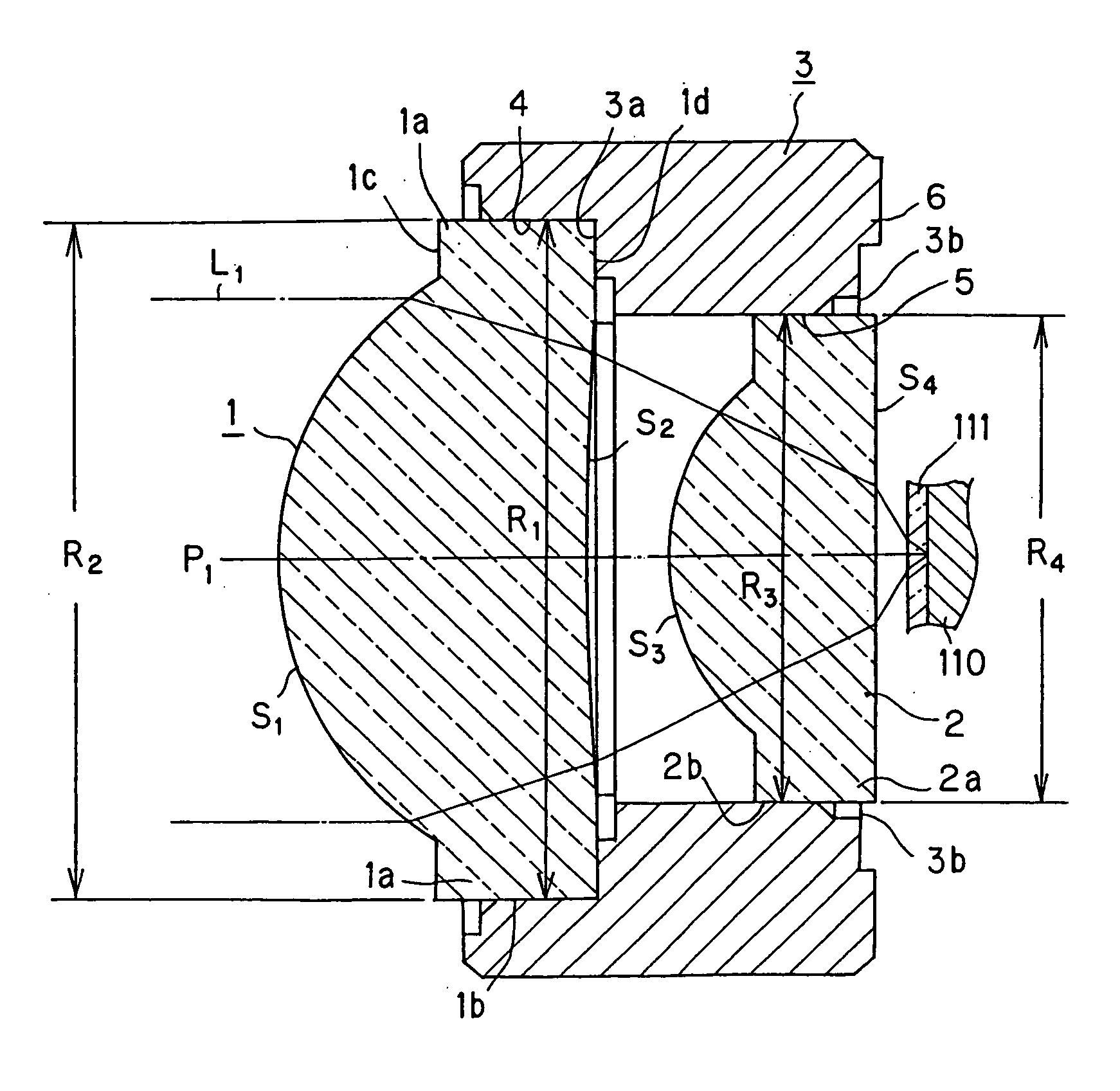
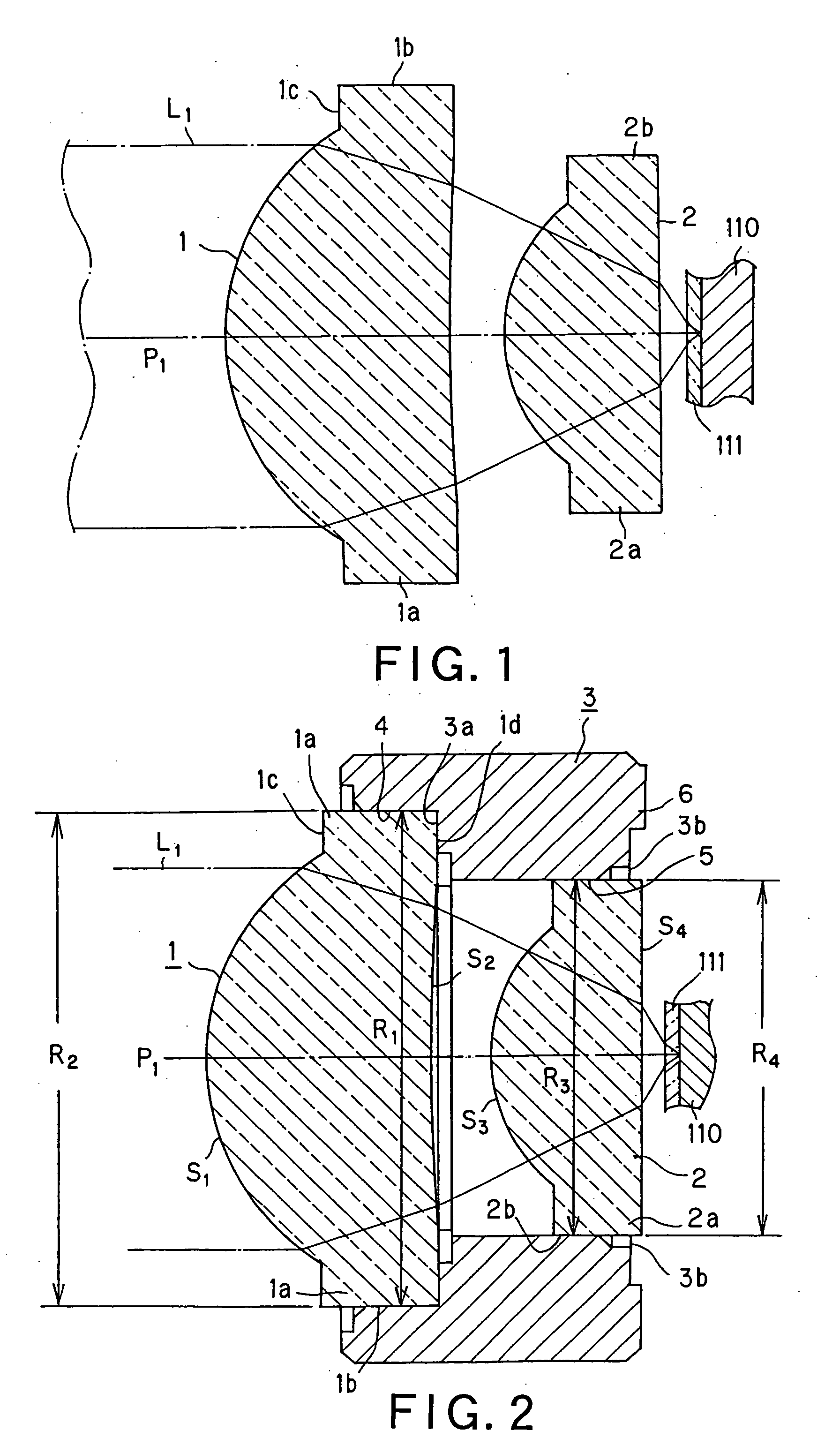
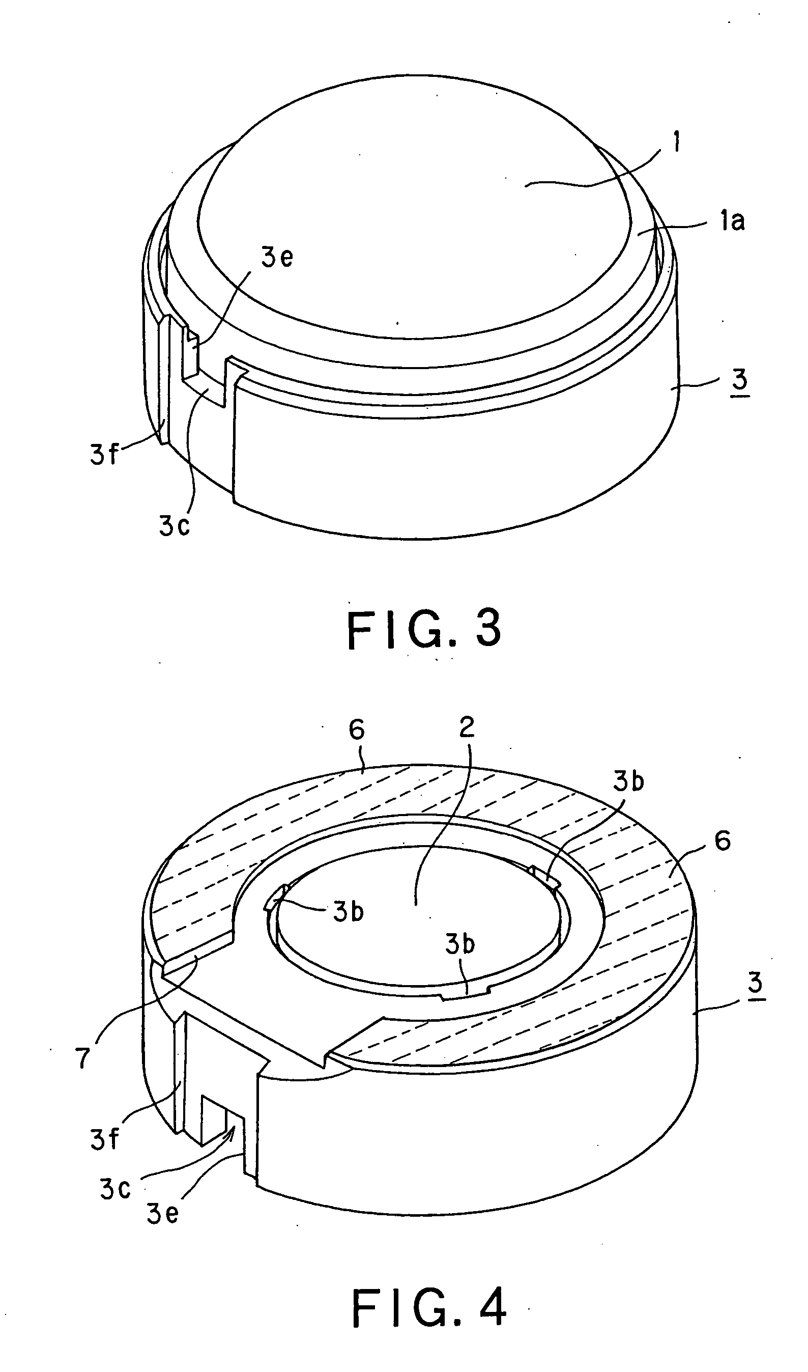
[0072] An objective lens unit of the present invention is made up by plural lenses each having a numerical aperture (NA) of 0.7 or larger. Specifically, the objective lens unit is made up by a double-lens set of two lenses 1, 2, and has a numerical aperture (NA) of 0.85, as shown in FIG. 1.

[0073] The objective lens unit of the present invention is built into an optical pickup device having a light source radiating the light beam with a center wavelength of 405 nm. That is, the objective lens unit according to the present invention is mainly used for condensing the light beam having a center wavelength of 405 nm.

[0074] In the following explanation, it is assumed that the objective lens unit has an effective diameter of 3 mm. Specifically, the manufacturing method for the objective lens unit of the present invention is the method for assembling an objective lens unit. An obj...


PUM

PropertyMeasurementUnit
diameteraaaaaaaaaa
center wavelengthaaaaaaaaaa
effective diameteraaaaaaaaaa

Abstract

An objective lens unit manufacturing apparatus for manufacturing an objective lens unit, with a numerical aperture not less than 0.7, made up by a plurality of lenses, includes a positioning mechanism (31) for positioning one lens (2) in a cylindrically-shaped lens holder (3) of a synthetic resin material, using another lens (1), already mounted and secured to the lens holder, as a reference, and for securing the one lens to the lens holder, for setting relative positions of the one and the other lenses.

Description

TECHNICAL FIELD [0001] This invention relates to a method and apparatus for producing an objective lens unit made up by a plural number of objective lenses and which may be used with advantage for an optical pickup used in turn for writing information signals on a optical recording medium and for reading out information signals recorded thereon. BACKGROUND ART [0002] Up to now, an optical recording medium, exemplified by an optical disc, has been used as a recording medium for information signals. An optical pickup device is used for writing or reading out information signals on or from an optical recording medium. The optical pickup device includes a semiconductor laser, as a light source for radiating a light beam to be illuminated on the optical recording medium, and an objective lens unit for condensing the light beam radiated from the semiconductor laser for illuminating the light beam to a signal recording surface of the optical recording medium. [0003] In the optical pickup d...

Claims


Application Information

Patent Timeline
Patent Type & Authority Applications(United States)
IPC IPC(8): G01B11/26G02B7/02G02B7/28G02B13/00G02B13/18G02B25/00G11B7/08G11B7/135G11B7/22
CPCG02B7/021G02B27/62G11B7/121G11B2007/13727G11B7/13922G11B7/22G11B7/1374
Inventor MAEDA, FUMISADANAGASHIMA, SHINICHI
Owner SONY CORP
Why Eureka
Try Eureka