Fiber grating pressure wave speed measurement system

a technology of pressure wave speed and fiber grating, which is applied in the direction of measurement devices, rapid change measurement, instruments, etc., can solve the problem of system more practicably limited detection speed

Inactive Publication Date: 2005-09-15
UDD ERIC +1
View PDF8 Cites 31 Cited by
  • Summary
  • Abstract
  • Description
  • Claims
  • Application Information

AI Technical Summary

Problems solved by technology

The system is more practically limited in detection speed by the mechanical response of very small fiber optic grating pressure sensors that have mechanical resonances for standard fibers in the 10s of MHz.

Method used


Image

  • Fiber grating pressure wave speed measurement system
  • Fiber grating pressure wave speed measurement system
  • Fiber grating pressure wave speed measurement system

Examples


Embodiment Construction

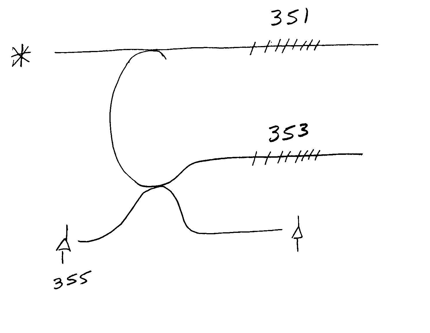
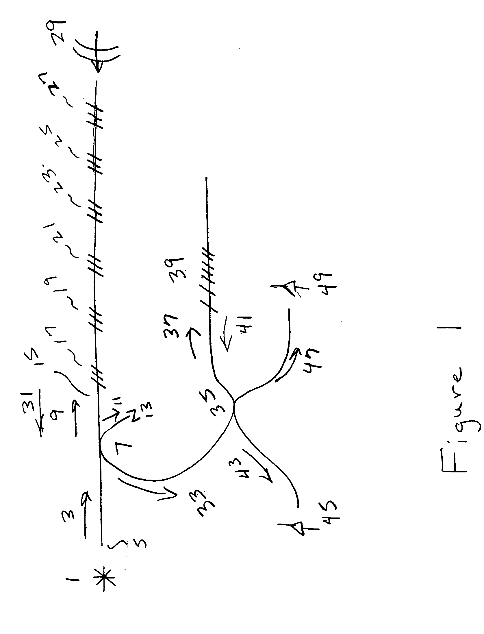
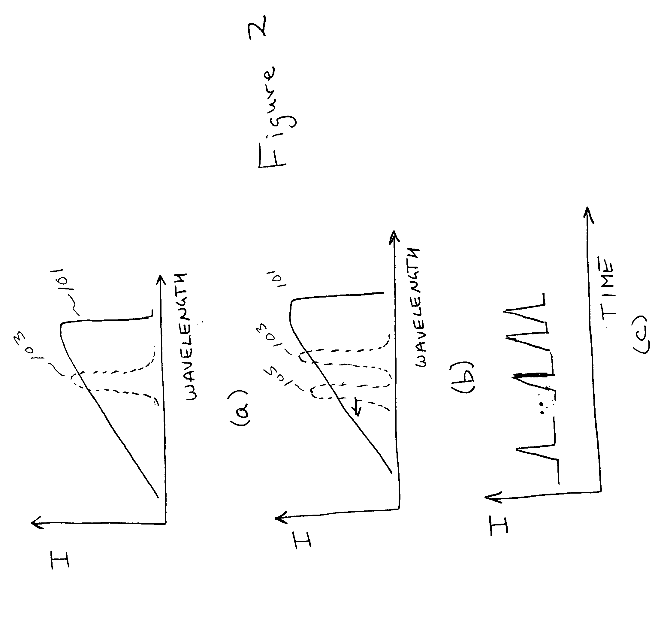
[0020]FIG. 1 shows a fiber optic pressure wave measurement system that is designed to measure the speed and amplitude of a high intensity blast pressure wave. A light source 1 that may be a spectrally broadband fiber light source couples the light beam 3 into the optical fiber end 5. The light beam 3 propagates to the fiber beamsplitter 7 where it is divided into the light beams 9 and 11. The light beam 11 propagates out to the terminated fiber 13 and exits the system. The light beam 9 propagates along the fiber 15 and a portion of the light beam 9 is reflected off the fiber grating sensors 17, 19, 21, 23, 25, and 27. These fiber grating sensors may be at different wavelengths but in one embodiment that has good signal to noise ratio all are at substantially the same wavelength. When a blast pressure wave 29 is directed toward the fiber grating sensor 27 it is at first compressed and later destroyed by the passage of the high intensity pressure wave 29. This results in the spectral ...


PUM


Abstract

A fiber grating strain sensing system is used to locate and characterize a high speed environmental event that destroys one or more fiber grating strain sensors as it passes them. The system is very suitable for the detection and characterization of a high intensity pressure wave such as a blast wave due to a detonation. A fiber grating strain sensor is oriented so that the high speed environmental effect passes over it and its reflective spectral profile changes as portions of the fiber grating strain sensor are destroyed. The reflective spectral profile from one or more fiber grating strain sensors are then mixed with the spectral profile of an optical filter onto a high speed output detector. A reference detector may be used to normalize the output signal. The spectral profiles of the fiber grating strain sensors and optical filter may be arranged in several ways that are effective including substantially matching both profiles, establishing opposite spectral slopes and utilization of an optical filter with a substantially flat spectral profile.

Description

[0001] This application claims the benefit of U.S. Provisional Application No. 60 / 552,846 by Eric Udd, Sean Calvert, Michele Winz, Jason Mooney and Nicholas Ortyl, “Fiber Optic Grating Systems”, filed Mar. 12, 2004.BACKGROUND OF THE INVENTION [0002] This disclosure describes means to detect the location and speed of a high speed pressure wave that might be encountered after detonation. [0003] This invention relates generally to fiber optic grating systems and more particularly, to the measurement of strain fields using fiber optic grating sensors and their interpretation to assess the speed, characteristics and location of a pressure wave. Typical fiber optic grating sensor systems are described in detail in U.S. Pat. Nos. 5,380,995, 5,402,231, 5,592,965, 5,841,131 and 6,144,026. All of these patents teaching are background for the present invention which optimizes the fiber grating sensor detection, localization and characterization of high speed pressure waves. [0004] The need for...

Claims


Application Information

Patent Timeline
Patent Type & Authority Applications(United States)
IPC IPC(8): G02B6/00
CPCG01L23/16G02B6/022
Inventor UDD, ERICCALVERS, SEAN GEOFFREY
Owner UDD ERIC
Why Eureka
Try Eureka