
Image blur correcting device

a technology of image blur and correcting device, which is applied in the field of image blur correcting device, can solve the problems of increased delay, phase delay, and phase delay, and achieve the effect of enhancing anti-vibration performan

Inactive Publication Date: 2005-09-15
FUJI PHOTO OPTICAL CO LTD
View PDF3 Cites 17 Cited by
  • Summary
  • Abstract
  • Description
  • Claims
  • Application Information

AI Technical Summary

Benefits of technology

"The invention provides an image blur correcting device that reduces image blur caused by vibration of an optical system. The device uses a digital filter with a characteristic that reduces phase delay of the output signal as the frequency of the input signal increases. This reduces the phase delay caused by processing time and improves antivibration performance. The device also includes an angular velocity sensor for detecting vibration and a digital filter that reduces phase delay at higher frequencies. Overall, the invention improves image quality and stability."

Problems solved by technology

However, when the angular velocity signal (input signal) is converted to the angle signal (output signal) by the digital filter, the phase delay with respect to each frequency of the angular velocity signal output from the angular velocity sensor contains not only a delay (90 degrees ideally) caused by the integration action, but also a delay caused by a time (processing time) needed to each processing.
Furthermore, the phase delay also occurs due to the processing time in the A / D converter for converting an analog angular velocity signal output from the angular velocity sensor to a digital signal.
Furthermore, when an angle signal achieved by the digital filter is output as an instruction signal indicating a movement position (target position) of an antivibration lens to a driving circuit for driving the antivibration lens, the phase delay is caused by the processing time in a D / A converter for converting a digital instruction signal to an analog signal.
Therefore, there is a problem that even when the phase of each frequency component of an angular velocity signal is delayed by 90 degrees through the digital integration, the phase delay is larger than 90 degrees because of the phase delay caused by the processing time as described above, and particularly the phase delay concerned is more increased as the frequency is higher, so that the antivibration performance is lowered.

Method used


Image

  • Image blur correcting device
  • Image blur correcting device
  • Image blur correcting device

Examples


Embodiment Construction

[0022] A preferred embodiment of an image blur correcting device according to the present invention will be described hereunder with reference to the accompanying drawings.

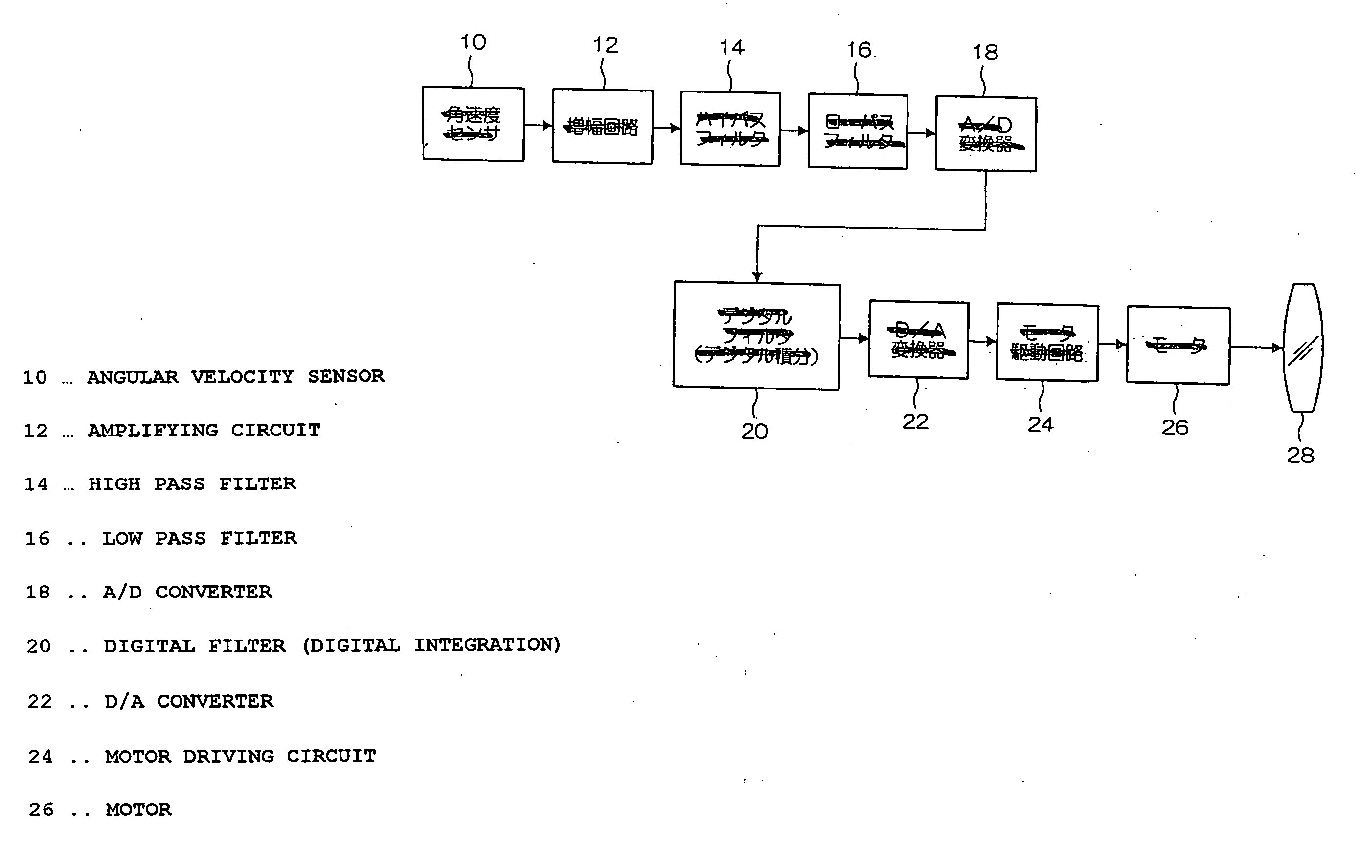
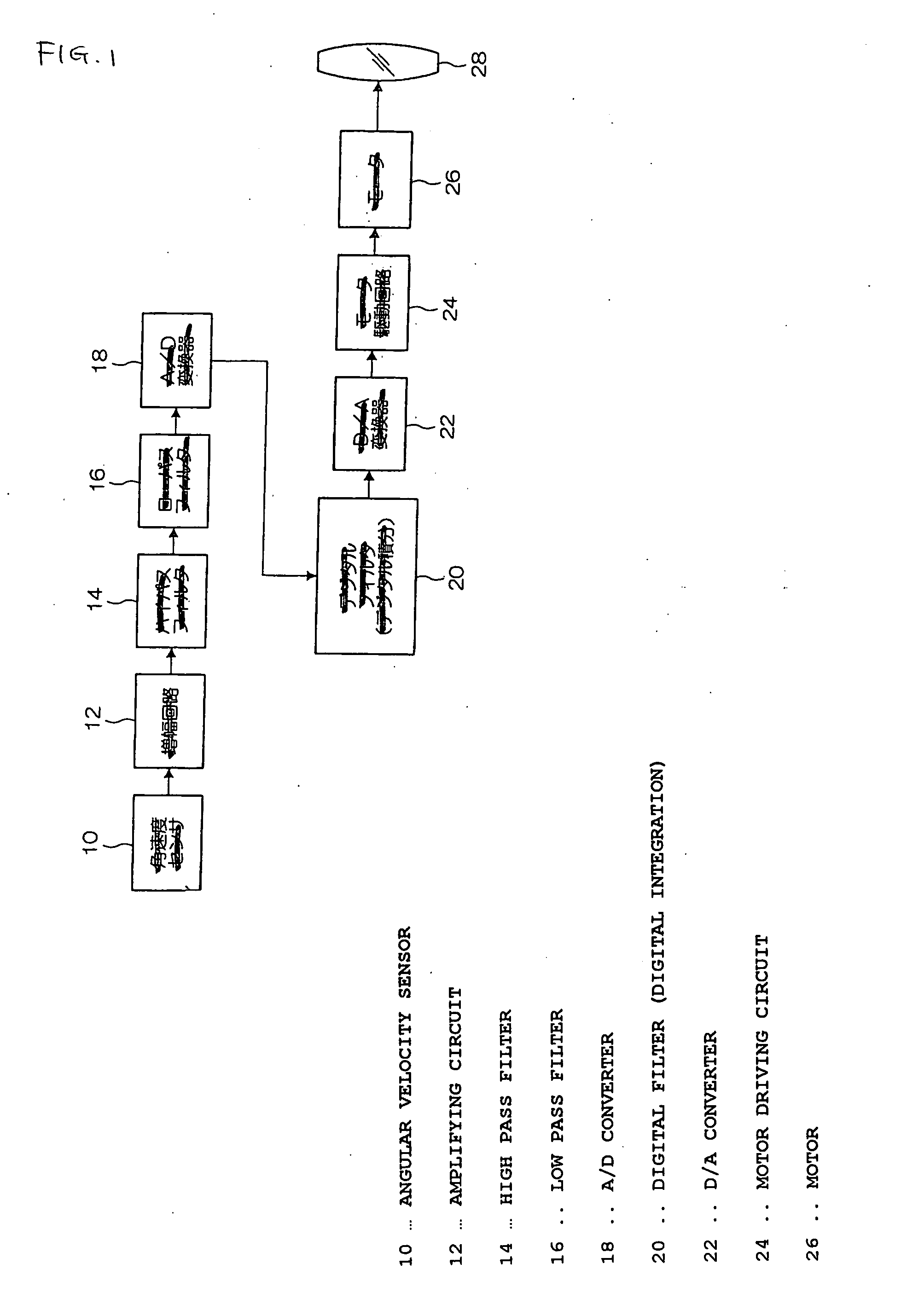
[0023]FIG. 1 is a diagram showing the internal construction of an embodiment of an image blur correcting device according to the present invention. The image blur correcting device is mounted in a lens device (taking lens) for a television camera, a movie camera, a still camera or the like, and an antivibration lens 28 is disposed in the lens device or an optical system of the camera or the like in which the image blur correcting device is mounted so that it is movable in the up-and-down direction (vertical direction) and in the right-and-left direction (horizontal direction) within a plane perpendicular to the optical axis. The antivibration lens 28 is driven in the up-and-down direction or in the right-and-left direction by a motor 26, and it is moved to an image blur correcting position (a position at which im...


PUM


Abstract

An image blur correcting device for reducing phase delay of an angle signal caused by the processing time of filter operation, etc. with a filter characteristic of a digital filter and enhancing antivibration performance in the image blur correcting device for detecting vibration of an optical system of an taking lens or the like by an angular velocity sensor and controlling an antivibration lens on the basis of an angle signal achieved by digitally integrating an angular velocity signal from the angular velocity sensor with a digital filter.

Description

BACKGROUND OF THE INVENTION [0001] 1. Technical Field of the Invention [0002] The present invention relates to an image blur correcting device, and particularly to an image blur correcting device for correcting (preventing) image blur of a camera due to vibration. [0003] 2. Description of the Related Art [0004] For example, as an image blur correcting device of a television camera is known a device in which an antivibration lens is disposed in an image pickup optical system so as to be freely movable within a plane perpendicular to the optical axis, and when a camera (the image pickup optical system of the camera) is vibrated, the antivibration lens is driven by an actuator so as to offset the image blur caused by the vibration, thereby correcting the image blur. For example, according to the image blur correcting device disclosed in JP-A-2002-229089, the vibration applied to the camera is detected by a vibration detecting sensor (angular velocity sensor, acceleration sensor or the ...

Claims


Application Information

Patent Timeline
Patent Type & Authority Applications(United States)
IPC IPC(8): H04N5/232G03B5/00
CPCG03B5/00G03B2205/0007H04N5/23287H04N5/23248G03B2217/005H04N23/68H04N23/687
Inventor MORIYA, CHIKATSU
Owner FUJI PHOTO OPTICAL CO LTD
Learn More