
Thermal management systems for battery packs

a technology of thermal management system and battery pack, which is applied in the direction of safety/protection circuit, electric vehicle, metal-working apparatus, etc., can solve the problems of severe effect on battery life, shortening battery life, and accumulating heat during the cooling process, and achieve the effect of enhancing the cooling effect of fluid

Active Publication Date: 2005-09-15
BLACK & DECKER INC
View PDF27 Cites 213 Cited by
  • Summary
  • Abstract
  • Description
  • Claims
  • Application Information

AI Technical Summary

Benefits of technology

[0009] According to yet another aspect of the present invention, a fluid is disposed in a battery pack housing and in surrounding contact with the cells of the battery pack. The battery pack housing includes at least one heat conductor metal plate in contact with the fluid and exposed to an exterior of the housing. According to a still further aspect of this invention, a stirring mechanism is provided for stirring the fluid within the housing for enhancing the cooling affect of the fluid around the cells. According to yet another embodiment of the present invention, the fluid around the cells is withdrawn and a cooled fluid can be inserted into the housing for cooling the cells.
[0018] According to yet another aspect of the present invention, a battery system is provided including a housing having a plurality of cells disposed in the housing. A Theological fluid is disposed in the housing and an inductor coil is disposed in the housing for generating a magnetic field within the housing for causing circulation of the Theological fluid within the housing. The Theological fluid is heat conducting and, therefore, provides cooling of the battery cells as the rheological fluid flows past the cells and conducts the heat away from the battery cells.

Problems solved by technology

Also, during charging of the battery pack, heat is likewise accumulated during the charging process.
The heat created during discharge of the batteries as well as charging of the batteries which, in turn, leads to increased temperatures, may have a severe effect on the life expectancy and performance of the batteries.
Likewise, if the batteries become too hot during use, battery life will be cut short.
Also, if a battery is below a certain threshold temperature, it will be too cold to charge and must be warmed before charging.
This will lead to a decline in the performance of the entire pack.

Method used


Image

  • Thermal management systems for battery packs
  • Thermal management systems for battery packs
  • Thermal management systems for battery packs

Examples


Embodiment Construction

[0051] The following description of the preferred embodiment(s) is merely exemplary in nature and is in no way intended to limit the invention, its application, or uses.

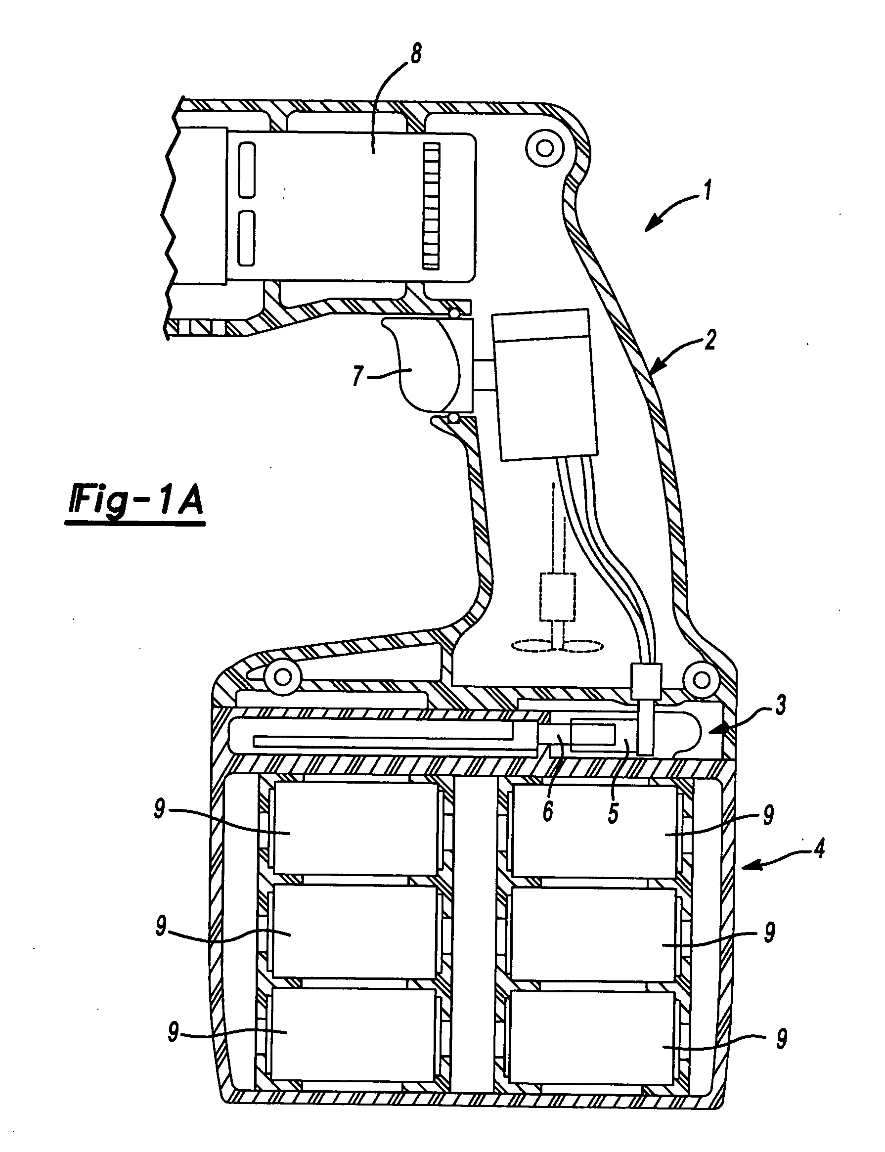
[0052] With reference to FIG. 1, a cordless device, such as a power tool, is illustrated and designated with reference numeral 1. The cordless device 1 ordinarily includes a clam shell type housing 2. The housing 2 includes a mechanism 3 to couple the housing 2 with a battery pack 4. The cordless device 1 includes electrical elements 5 which couple with corresponding electrical elements 6 of the battery pack 8. The device 1 includes a trigger 7 which is activated for energizing a motor 8 provided within the housing 2, as is well known in the art. Normally, a plurality of battery cells 9 are disposed within the battery pack 4.

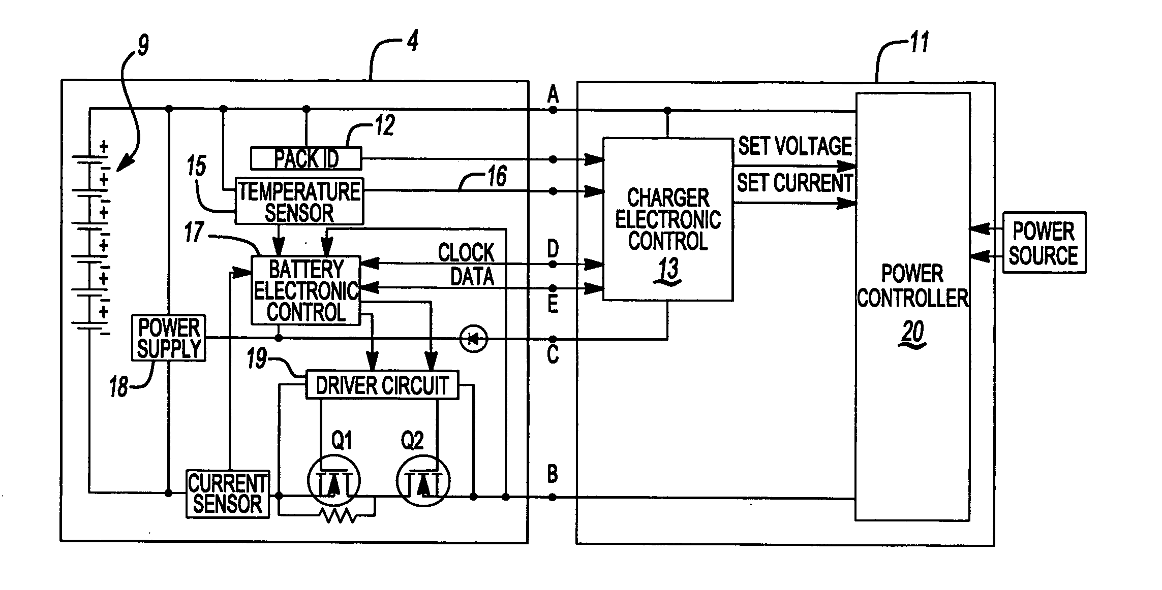
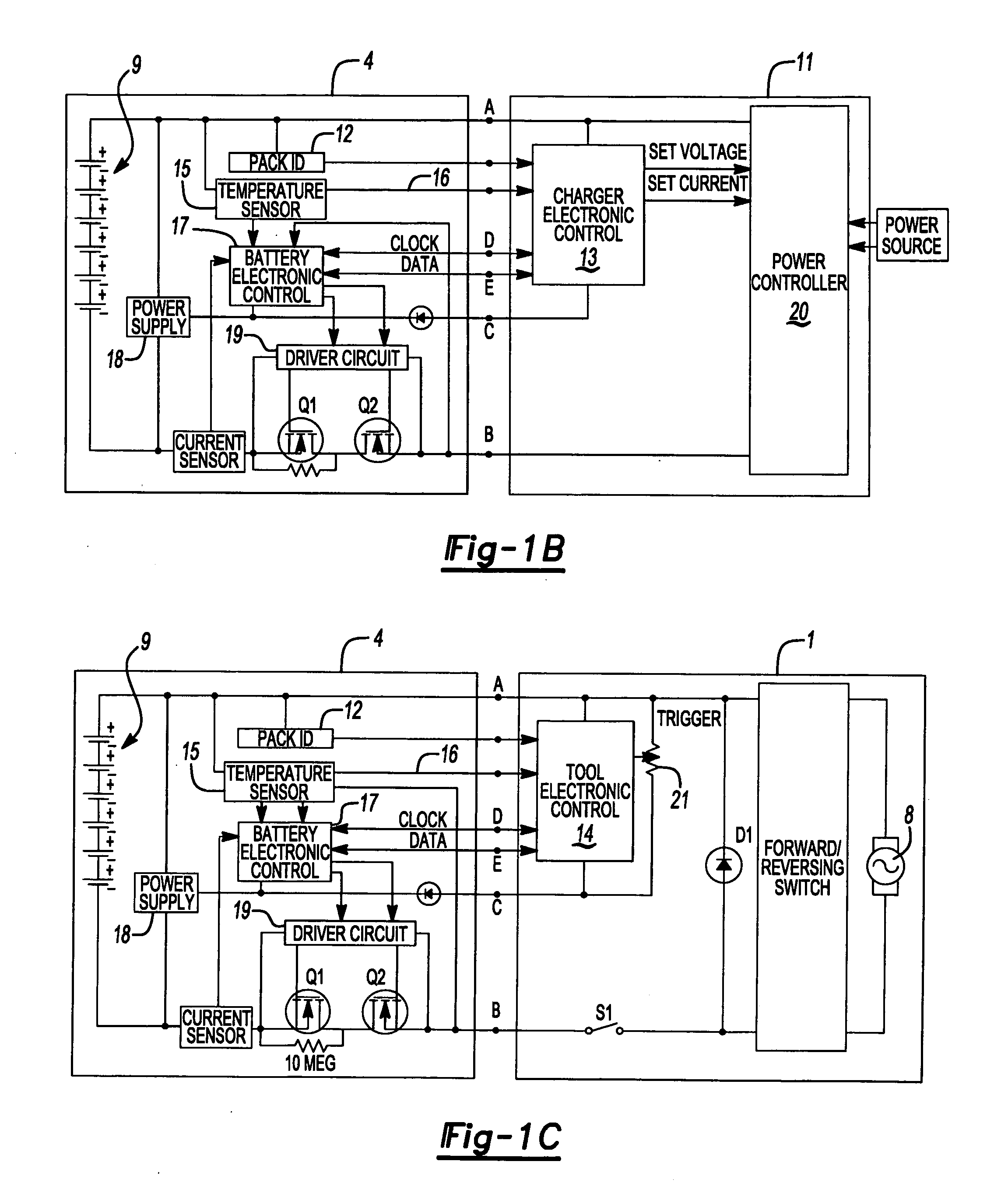
[0053] With reference to FIG. 1B, the functional control features of a battery pack 4 and battery charger 11, according to the principles of the present invention, will be described. The power ...


PUM

PropertyMeasurementUnit
temperatureaaaaaaaaaa
sizeaaaaaaaaaa
melt temperatureaaaaaaaaaa

Abstract

A cordless power tool has a housing which includes a mechanism to couple with a removable battery pack. The battery pack includes one or more battery cells as well as a system to dissipate heat from the battery pack.

Description

CROSS-REFERENCE TO RELATED APPLICATIONS [0001] This application claims the benefit of U.S. Provisional Application No. 60 / 551,891, filed on Mar. 10, 2004, the disclosure of which is incorporated herein by reference.FIELD OF THE INVENTION [0002] The present invention relates to battery cooling systems and, more specifically, to systems for cooling batteries for cordless power tools. BACKGROUND OF THE INVENTION [0003] Cordless products which use rechargeable batteries are prevalent throughout the workplace as well as in the home. From housewares to power tools, rechargeable batteries are used in numerous devices. Ordinarily, nickel-cadium or nickelmetal-hydride battery cells are used in these devices. Since the devices use a plurality of battery cells, the battery cells are ordinarily packaged as battery packs. These battery packs couple with the cordless devices and secure to the device. The battery pack may be removed from the cordless device and charged in a battery charger or char...

Claims


Application Information

Patent Timeline
Patent Type & Authority Applications(United States)
IPC IPC(8): B23B45/02B25F5/00H01M2/10H01M2/34H01M6/50H01M10/42H01M10/44H01M10/46H01M10/48H01M10/50H02J7/00H02J7/02
CPCB25F5/008H02J2007/0098H01M2/1055H01M2/1094H01M2/348H01M10/425H01M10/44H01M10/46H01M10/486H01M10/5004H01M10/5014H01M10/5022H01M10/503H01M10/5046H01M10/5048H01M10/5053H01M10/5061H01M10/5063H01M10/5067H01M10/5075H01M10/5085H01M10/5089H01M2200/00H01M2200/10H02J7/0004H02J7/0029H02J7/0031H02J7/0091H02J7/027H01M2/105H01M10/633H01M10/6563H01M10/6551H01M10/6567H01M10/6552H01M10/643H01M10/6554H01M10/6572H01M10/6235H01M10/6561H01M10/613H01M10/659H01M10/656H02J7/00036H01M10/4257H02J7/00047Y02E60/10H02J7/00309H02J7/0047H02J7/007194H01M50/213H01M50/24H01M50/581
Inventor YAHNKER, CHRISTOPHER R.BROTTO, DANIELE C.EKSTROM, ERIK A.SEMAN, ANDREW E. JR.CARRIER, DAVID A.PHILLIPS, STEVEN J.DOYLE, MICHAEL C.TRINH, DANH T.SPENCER, WILLIAM D.FRANCIS, JEFFREY J.WHITE, DANIEL J.
Owner BLACK & DECKER INC
Learn More