Ultrasonic imaging method and apparatus

a technology of ultrasonic imaging and apparatus, applied in the direction of instruments, catheters, ultrasonic/sonic/infrasonic image/data processing, etc., can solve the problems of complex apparatus, limited frequency band to be used, and not generally generated ultrasonic images, etc., to achieve the effect of expressing differences of tissues more clearly

Inactive Publication Date: 2005-09-15
FUJIFILM HLDG CORP +1
View PDF3 Cites 20 Cited by
  • Summary
  • Abstract
  • Description
  • Claims
  • Application Information

AI Technical Summary

Benefits of technology

[0011] In view of the above points, an object of the present invention is to provide ultrasonic imaging method and apparatus capable of expressing differences of tissues more clearly by focusing attention on the relationship between characteristics of an object and frequency characteristics of received ultrasonic waves.

Problems solved by technology

However, the ultrasonic image is not generally generated in consideration of the relationship between the characteristics of the object and the frequency characteristics of the received ultrasonic waves.
However, even in the case, the frequency band to be used is limited within a range usable in one ultrasonic probe or not particularly specified.
However, to compare the two Fourier transformed signals, they must be timed and the apparatus becomes complicated.
In addition, since the two Fourier transformed signals are compared based on the signals measured in experimental systems with completely different settings, not only bone-specific information but also factors due to setting error and so on influence the signals, and thereby, measurement reliability is low.
However, this document does not disclose based on what the weighting addition is performed on the intensity signals.

Method used


Image

  • Ultrasonic imaging method and apparatus
  • Ultrasonic imaging method and apparatus
  • Ultrasonic imaging method and apparatus

Examples


first embodiment

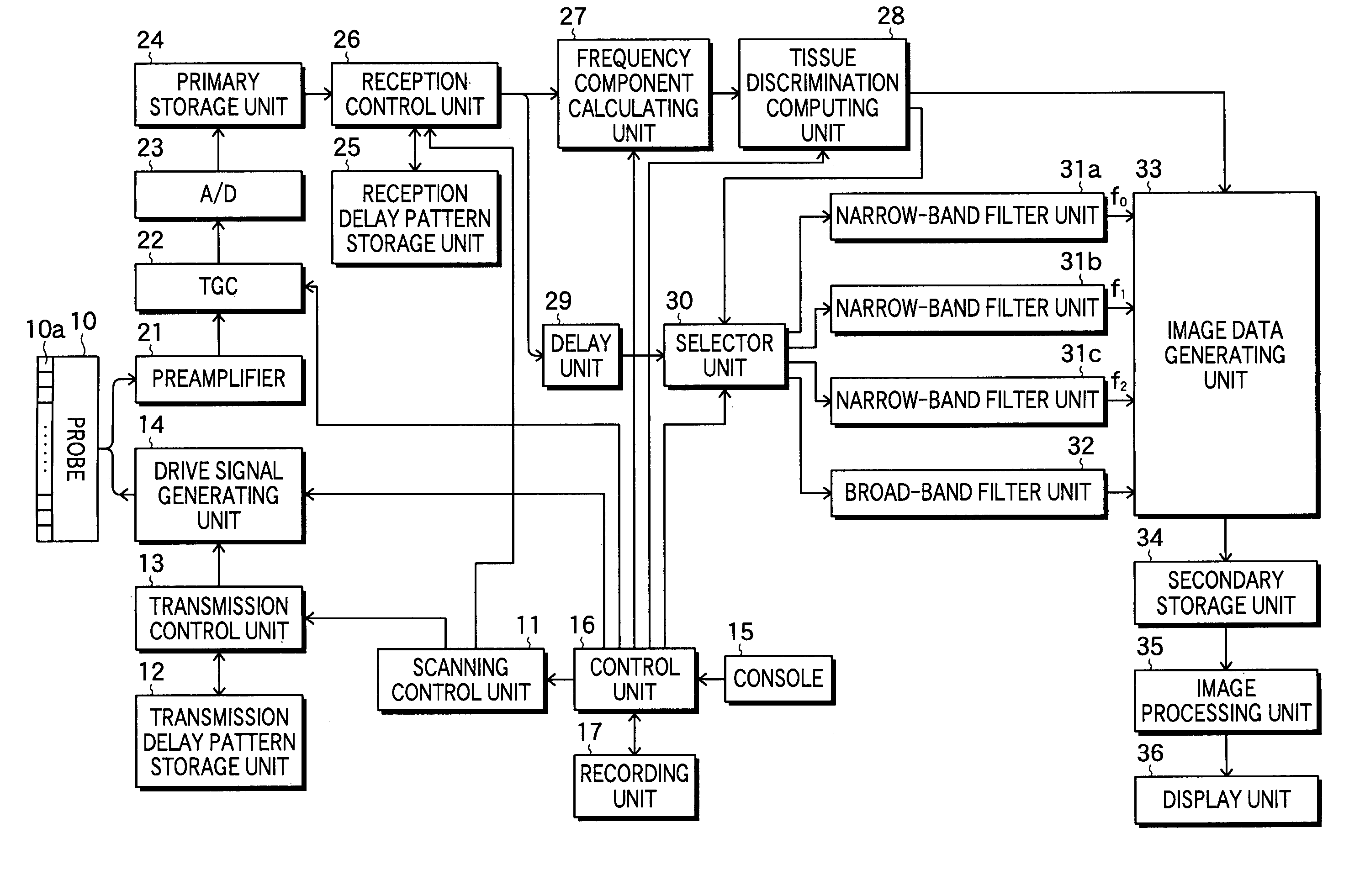
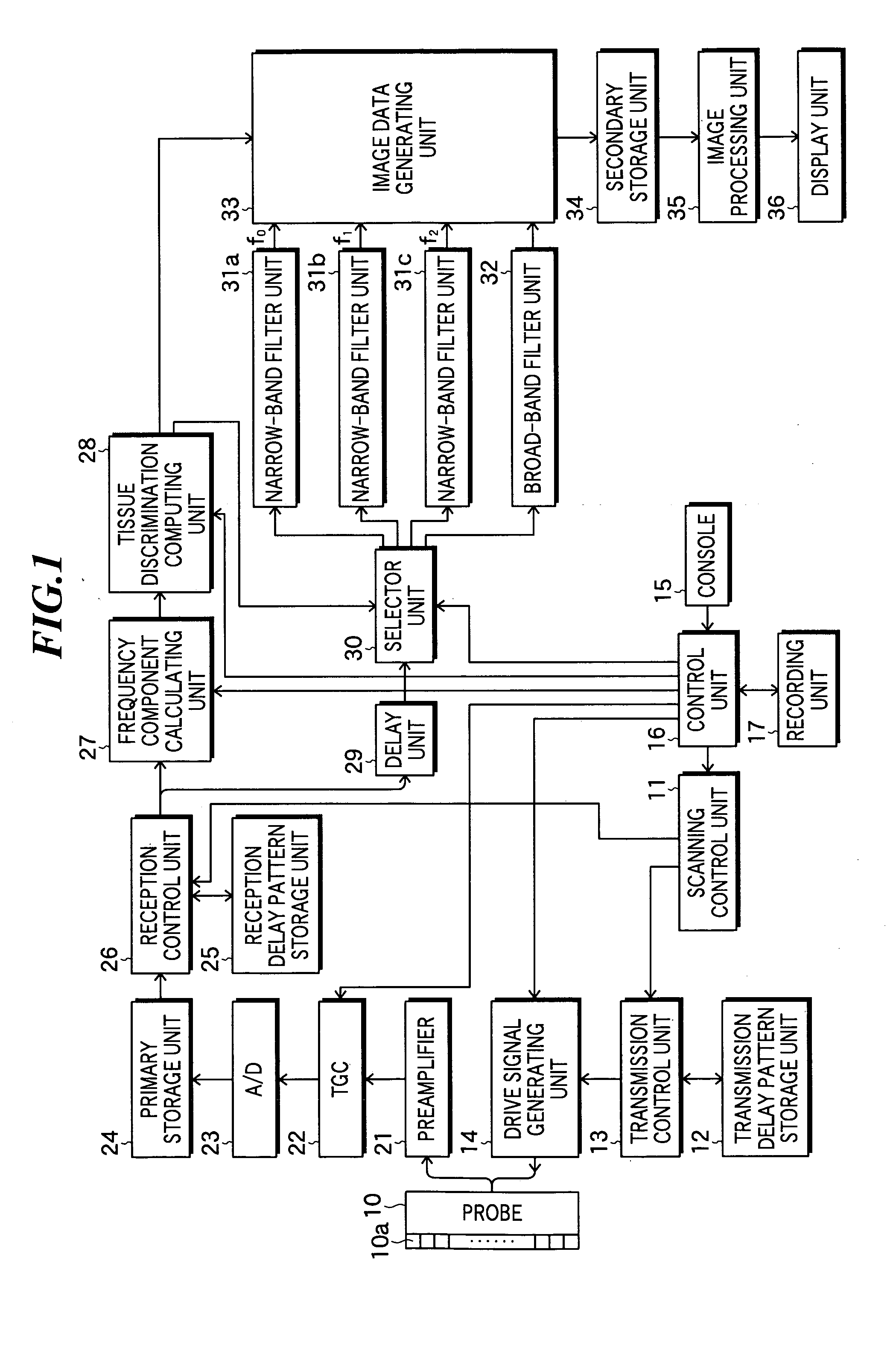
[0022]FIG. 1 is a block diagram showing the constitution of an ultrasonic imaging apparatus according to the present invention. The ultrasonic imaging apparatus according to the embodiment includes an ultrasonic probe 10, a scanning control unit 11, a transmission delay pattern storage unit 12, a transmission control unit 13, and a drive signal generating unit 14.

[0023] The ultrasonic probe 10 includes plural ultrasonic transducers 10a arranged in a one-dimensional or two-dimensional manner to form a transducer array, and the ultrasonic probe 10 is used by being abutted on an object to be inspected. These ultrasonic transducers 10a transmit ultrasonic beams based on applied drive signals, and receive propagating ultrasonic echoes to output detection signals.

[0024] Each ultrasonic transducer is constituted by a vibrator in which electrodes are formed on both ends of a material having a piezoelectric property (piezoelectric material) such as a piezoelectric ceramic represented by PZT...

second embodiment

[0048]FIG. 4 is a schematic diagram showing an ultrasonic imaging apparatus according to the present invention. This ultrasonic imaging apparatus is an ultrasonic CT for mammary cancer diagnosis, and includes an ultrasonic transmitting unit 40 for transmitting ultrasonic waves to an object to be inspected (breast of a patient) 90, an ultrasonic receiving unit 50 for receiving ultrasonic waves transmitted through the object 90, a signal processing unit 60 connected to the ultrasonic transmitting unit 40 and ultrasonic receiving unit 50, and a tank 70 in which water or other acoustic medium 80 is put. In the tank 70, acoustic windows 71 and 72 are provided in order to obtain the match of acoustic impedance between the ultrasonic transmitting unit 40 and ultrasonic receiving unit 50 and the acoustic medium 80.

[0049]FIG. 5 shows an arrangement example of transmitting element arrays to be used for the ultrasonic transmitting unit and receiving element arrays to be used for the ultrasonic...


PUM


Abstract

Ultrasonic imaging method and apparatus capable of expressing differences of tissues more clearly by focusing attention on the relationship between characteristics of an object and frequency characteristics of received ultrasonic waves. The apparatus includes an ultrasonic transmitting and receiving unit for transmitting and receiving ultrasonic waves to obtain a detection signal; a frequency component calculating unit for calculating plural frequency components from data based on the detection signal; a tissue discrimination computing unit for obtaining characteristics, which change depending on tissues of the object, based on the calculated plural frequency components; a selector unit for selecting at least one of plural frequency bands corresponding to at least one tissue displayed within one screen in accordance with the obtained characteristics; and an image data generating unit for generating image data representing an ultrasonic image based on intensity of the detection signal in the selected frequency band.

Description

BACKGROUND OF THE INVENTION [0001] 1. Field of the Invention [0002] The present invention relates to ultrasonic imaging method and apparatus for performing imaging of organs, bones, etc. within a living body by transmitting and receiving ultrasonic waves so as to generate ultrasonic images to be used for diagnosis. [0003] 2. Description of a Related Art [0004] In an ultrasonic imaging apparatus to be used for medical application, normally, an ultrasonic probe including plural ultrasonic transducers having functions of transmitting and receiving ultrasonic waves is used. Using such an ultrasonic probe, an object to be inspected is scanned by an ultrasonic beam formed by synthesizing plural ultrasonic waves, and the ultrasonic echoes reflected from the object are received, and thereby, image information on the object is obtained based on the intensity of the ultrasonic echoes. Furthermore, two-dimensional or three-dimensional images on the object are reproduced based on the image info...

Claims


Application Information

Patent Timeline
Patent Type & Authority Applications(United States)
IPC IPC(8): A61B8/08A61B8/02A61B8/06A61B8/12G01S7/52
CPCG01S7/52036A61B8/08
Inventor TSUJITA, KAZUHIRO
Owner FUJIFILM HLDG CORP
Why Eureka
Try Eureka