Double-hull ore carrying vessel conversion from single-hull oil tanker and method of performing the same

Inactive Publication Date: 2005-09-22
NEU RICHARD W
View PDF35 Cites 12 Cited by
  • Summary
  • Abstract
  • Description
  • Claims
  • Application Information

AI Technical Summary

Benefits of technology

[0013] Another aspect of the invention comprises a method for achieving the conversion. In accordance with steps of the method of the present invention, a single hull vessel is provided with an outer hull surrounding at least one center cargo tank formed in an interior of the vessel. The center cargo tank is spaced from the outer hull by a port side longitudinal bulkhead and a starboard side longitudinal bulkhead and at least two spaced apart transverse bulkheads extending between the port and starboard side longitudinal bulkheads. An elevated floor preferably comprised of new bottom plating is installed in at least one of the center cargo tanks of the single-hull vessel to form a sealed compartment, or second hull separating the

Problems solved by technology

There has also been a long period of under-investment in the tanker industry as a whole.
Therefore, the value of these tankers has diminished.
However, because of new legislation and other regulations, this large existing fleet of single hull vessels is being prematurely forced out of service.
The number of double hull vessels suited for carrying these bulk materials is relatively small and new construction of such vessels is relatively expensive and a time consuming process.
In fact, at the present time, there is a worldwide shortage of dry bulk shipping vessels includi

Method used


Image

  • Double-hull ore carrying vessel conversion from single-hull oil tanker and method of performing the same
  • Double-hull ore carrying vessel conversion from single-hull oil tanker and method of performing the same
  • Double-hull ore carrying vessel conversion from single-hull oil tanker and method of performing the same

Examples


Embodiment Construction

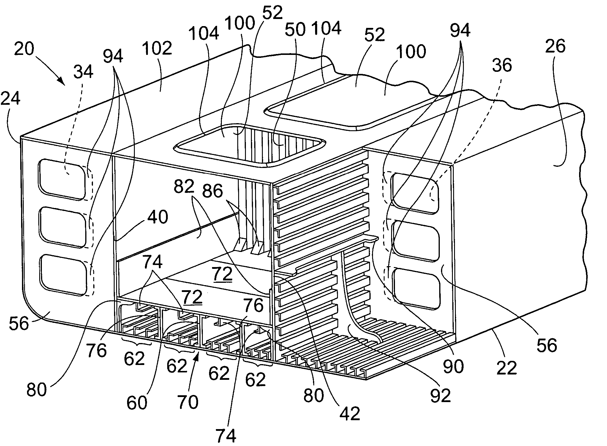
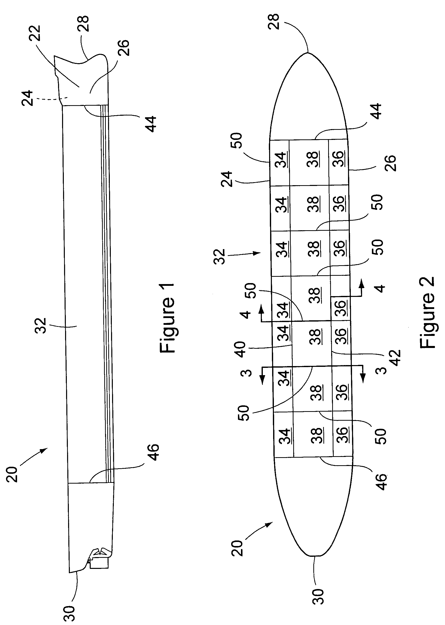
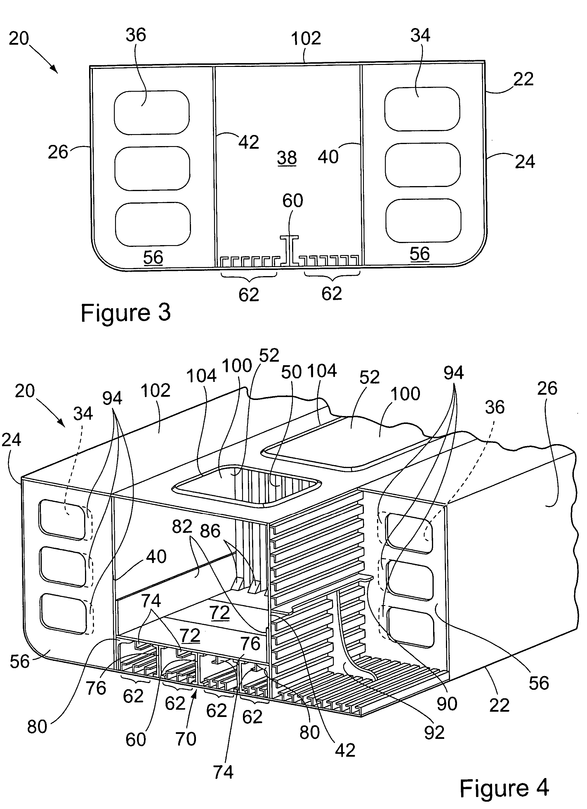
[0023]FIGS. 1-3 show a single hull vessel 20 that may be converted using the principles of the present invention. The vessel 20 has an outer hull structure 22 generally defining the shape and body of the vessel to which the remaining structure of the vessel is attached. As is customarily known in the art, the vessel has port and starboard sides 24,26, a bow 28 and a stern 30 with an amidships portion 32 of the vessel therebetween. The vessel also typically has a pilot house, accommodations, rigging and deck structure. These structures have been omitted from the drawings for the purposes of simplifying the explanation herein.

[0024] The vessel 20 shown in FIG. 2 is a typical single hull oil tanker. In the amidships 32 portion of the vessel, the vessel has a port side wing tank 34 running longitudinally along the port side 24 of the vessel and a starboard side wing tank 36 running longitudinally along a starboard side 26 of the vessel. Between the port and starboard wing tanks 34,36, ...


PUM


Abstract

A method for converting a single-hull vessel to a double hull vessel, and the converted double hull vessel, is disclosed. The single hull vessel to be converted has an outer hull surrounding a center cargo tank flanked by a port wing tank and a starboard wing tank, with spaced-apart transverse bulkheads extending between the port and starboard wing tanks to form one or more central tanks. An elevated floor is added to the central cargo tanks by installing new bottom plating spanning the transverse bulkheads and the sidewalls of the wing tanks. Support members are added to increase the strength of the elevated floor, the cargo tank, and the wing tanks, as needed. A sealed compartment is formed by the new elevated floor, the outer hull, and the sidewalls and bulkheads to protect the cargo from leaking out of the vessel should the integrity of the single hull be breached. The method achieves conversion of the single hull vessel to a double hull construction without breaching the integrity of the pre-existing single outer hull, and thus is faster and easier in converting single hull vessels to minimize cost of conversion and vessel outage.

Description

BACKGROUND OF THE INVENTION [0001] The present invention relates to the conversion of a single-hull vessel into a double hull vessel. More specifically, the present invention relates to the conversion of a single hull oil tanker into a double hull ore carrying vessel. Yet more specifically, the present invention relates to the conversion of a single hull vessel into a double hull vessel, wherein the single hull vessel has pre-existing port and starboard wing tanks flanking a center cargo tank and an elevated floor is added in the bottom of the center cargo tank spanning the sidewalls of the wing tanks to provide a sealed compartment interposed between the center cargo tank and the bottom of the outer single hull. The present invention also includes the installation of a hatch in a deck of the vessel to provide access to the center cargo tank from above. [0002] Currently, many single hull oil tanker marine vessels are approaching forced retirement because of the regulations in the sh...

Claims


Application Information

Patent Timeline
IPC IPC(8): B63B3/20B63B3/62B63B9/04B63B25/08
CPCB63B9/04B63B3/20B63B83/40
Inventor NEU, RICHARD W.
Owner NEU RICHARD W
Why Eureka
Try Eureka