

Continuous lamination of RFID tags and inlets
- Summary
- Abstract
- Description
- Claims
- Application Information
AI Technical Summary
Benefits of technology
Problems solved by technology
Method used
Image

Examples
Embodiment Construction
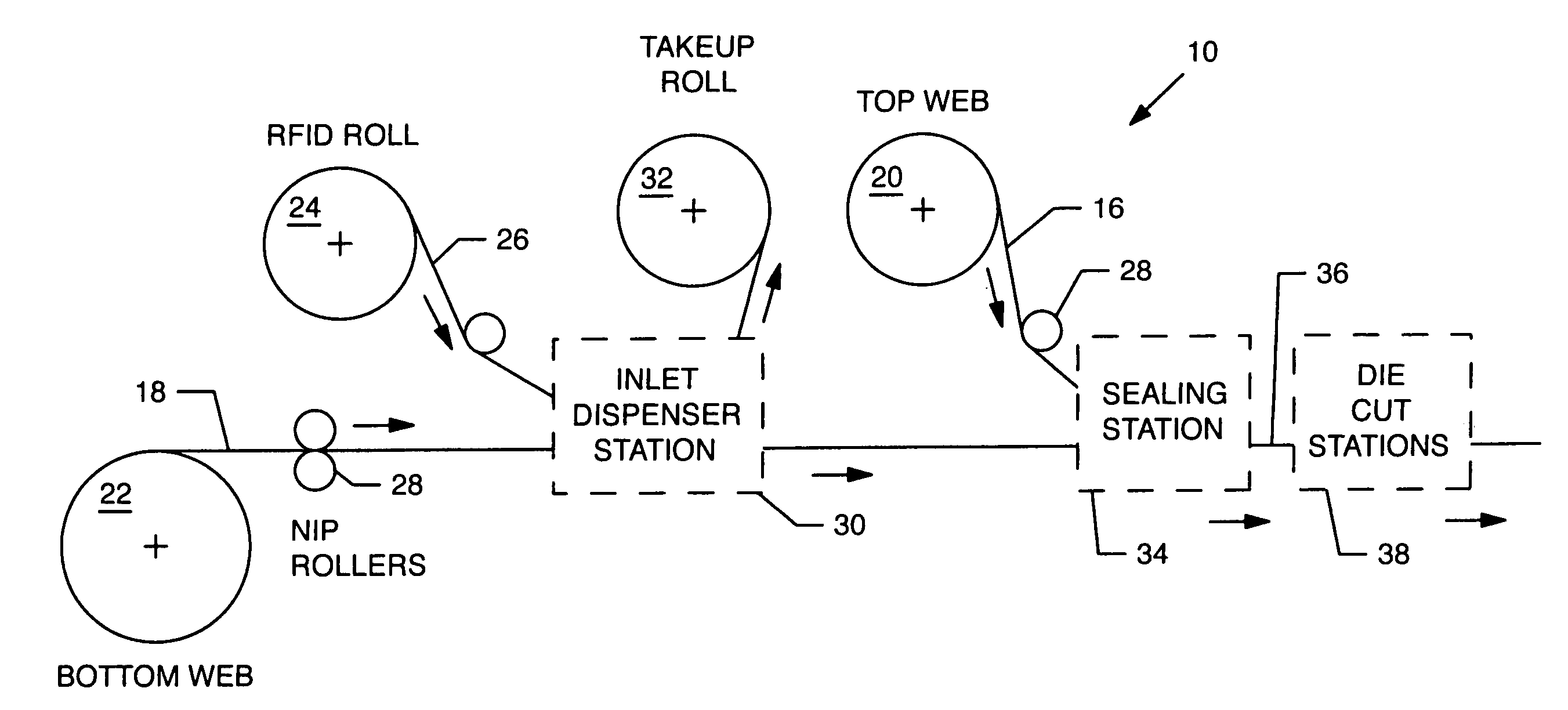
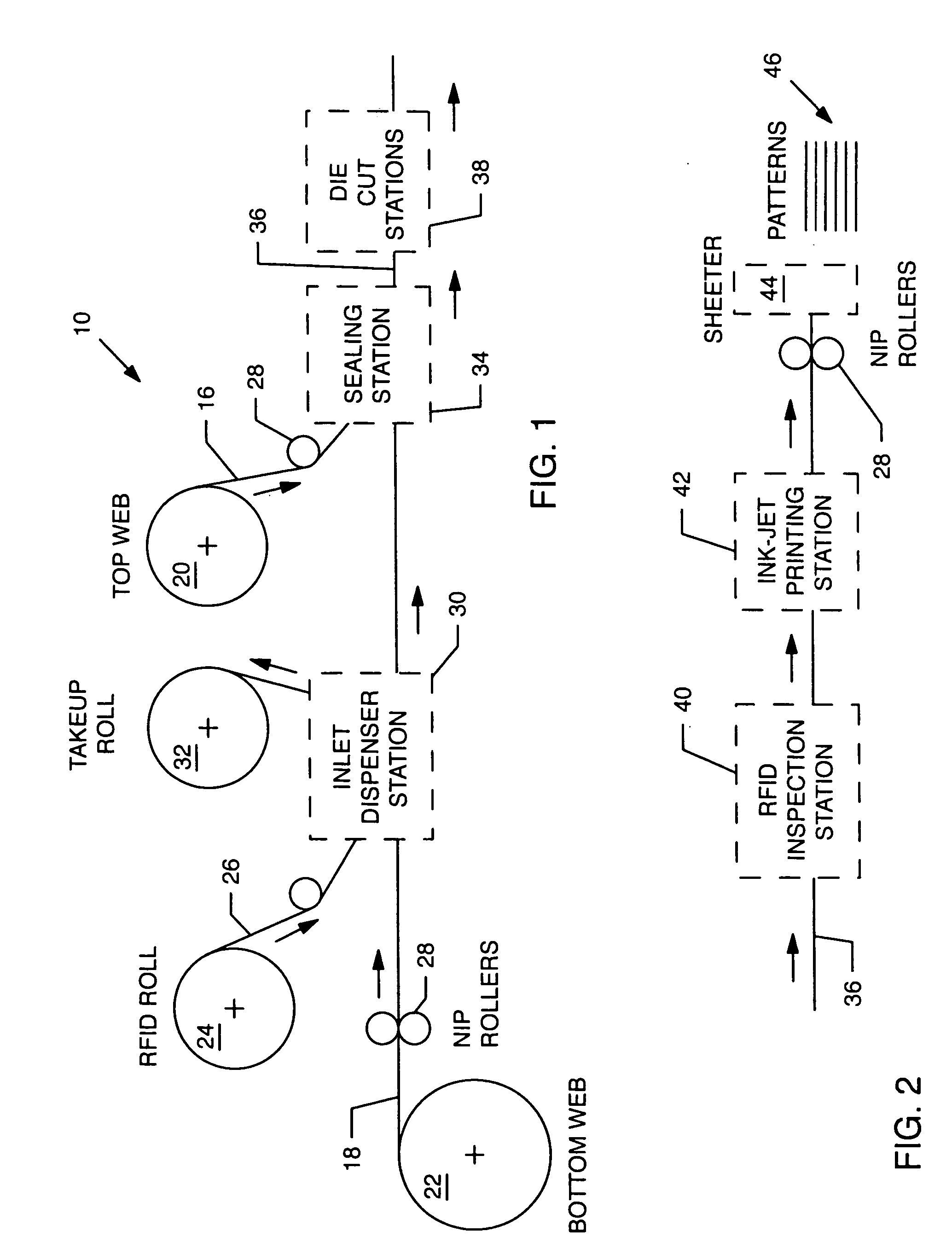
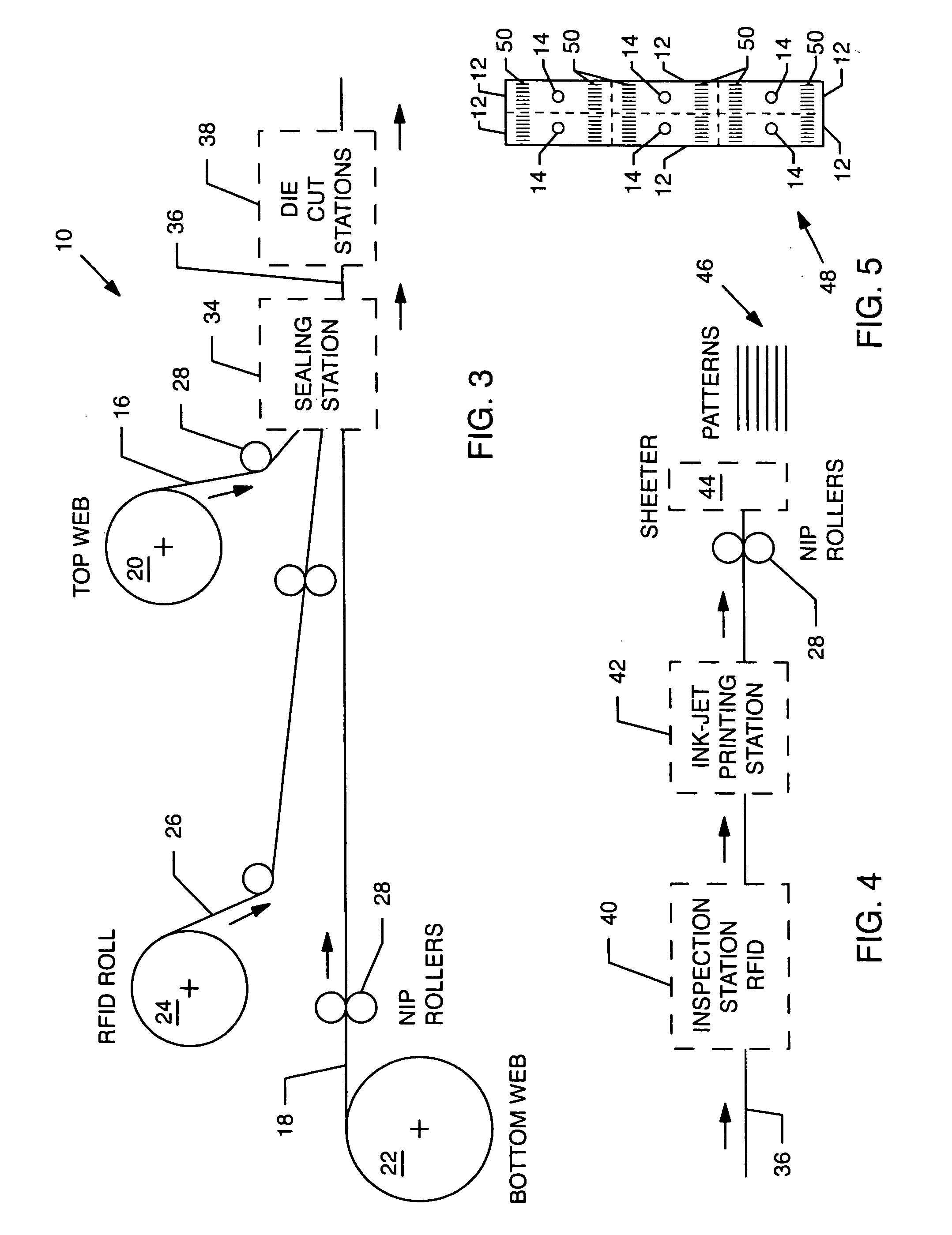
[0033] The present invention resides in a process for continuous lamination of radio frequency identification (RFID) tags. The manufacture of RFID tags from continuous rolls of pre-arranged, pre-fabricated RFID inlets provides an efficient and cost-effective method of making RFID tags. The process for continuous lamination of RFID tags includes a continuous lamination process of placing at least one RFID inlet between two substrates (i.e., a top substrate and a bottom substrate) made of plastic sheets or rolls of web. A continuous source of pre-arranged, pre-fabricated RFID inlets is provided. The RFID inlets on the continuous source of pre-arranged, pre-fabricated RFID inlets are spaced apart based upon a predetermined size and shape of tag.
[0034] The present invention permits the use of pre-fabricated RFID inlets manufactured by any technique known in the art, including but not limited to, printing of organic materials or traditional masking and etching techniques. With regard to...
PUM
| Property | Measurement | Unit |
|---|---|---|
| Length | aaaaa | aaaaa |
| Shape | aaaaa | aaaaa |
Abstract
Description
Claims
Application Information